


MacroSolid
QUICK START
You've installed the add-in – now what? In just a few steps, we’ll guide you through your first launch, understanding how it works, and basic configuration. Take a moment, and you’ll quickly start using MacroSolid effectively – making the most of its potential.
The demonstration version of the MacroSolid add-in is preconfigured to allow immediate use. However, it’s worth adjusting a few options to suit your individual needs.
SOLIDWORKS® Language Version Matters
If you're using the English version of SOLIDWORKS®, everything should work correctly. However, if you're using a different version, you need to synchronize the language settings in MacroSolid.
In the general options of MacroSolid, check and, if necessary, change the language in three different places. Mixing language versions may cause issues.
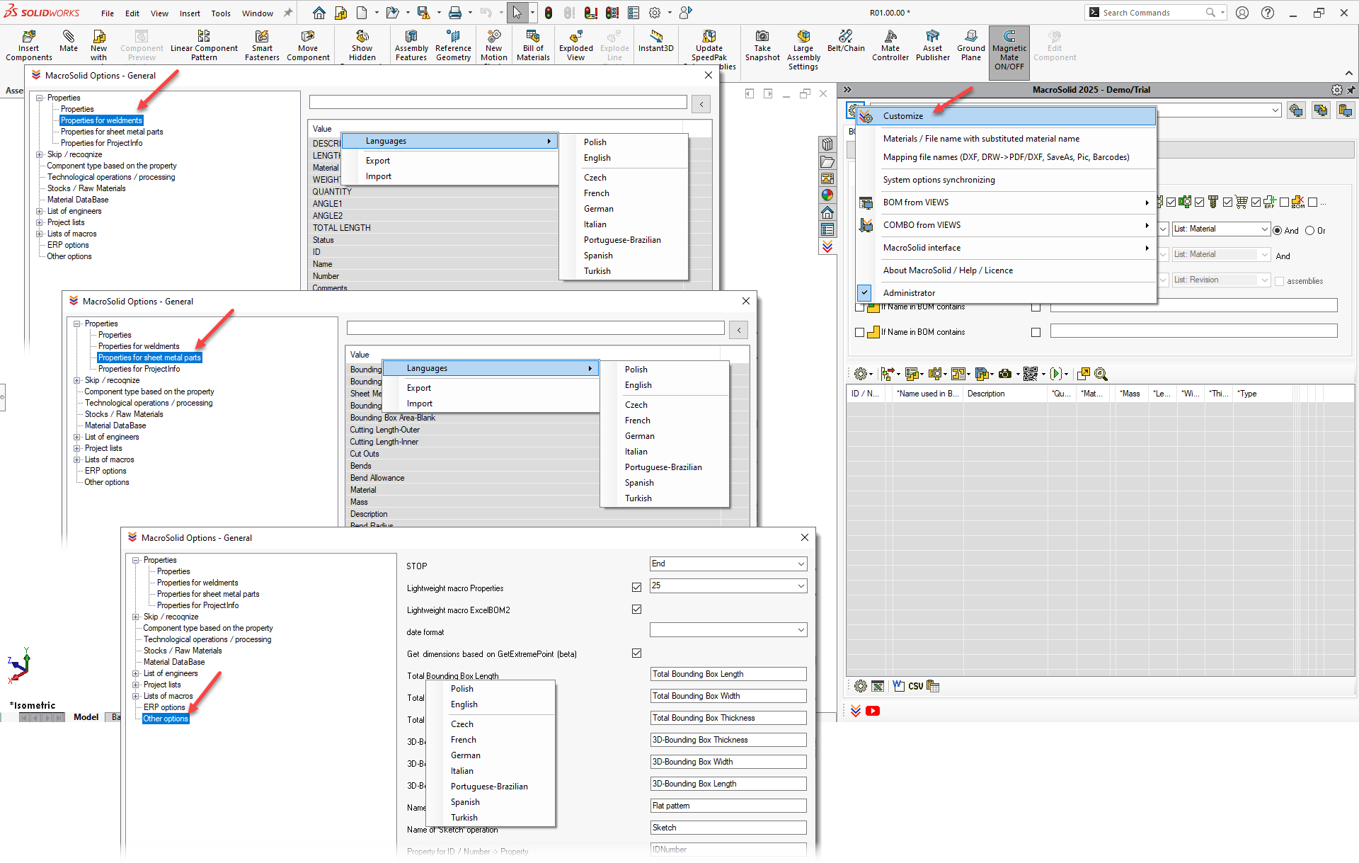
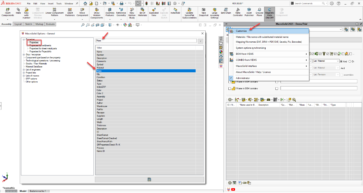
Customizing Property Names
This is a crucial step in the configuration.
Go to: General options → Customize.
On the list of properties, select the appropriate row and change the property name to match the one you use.
For example: instead of the default “Mass” enter “Weight”, instead of “Qty.” enter “Quantity”, etc.
⚠️ Don’t change the order of the list unless necessary – the order also matters.
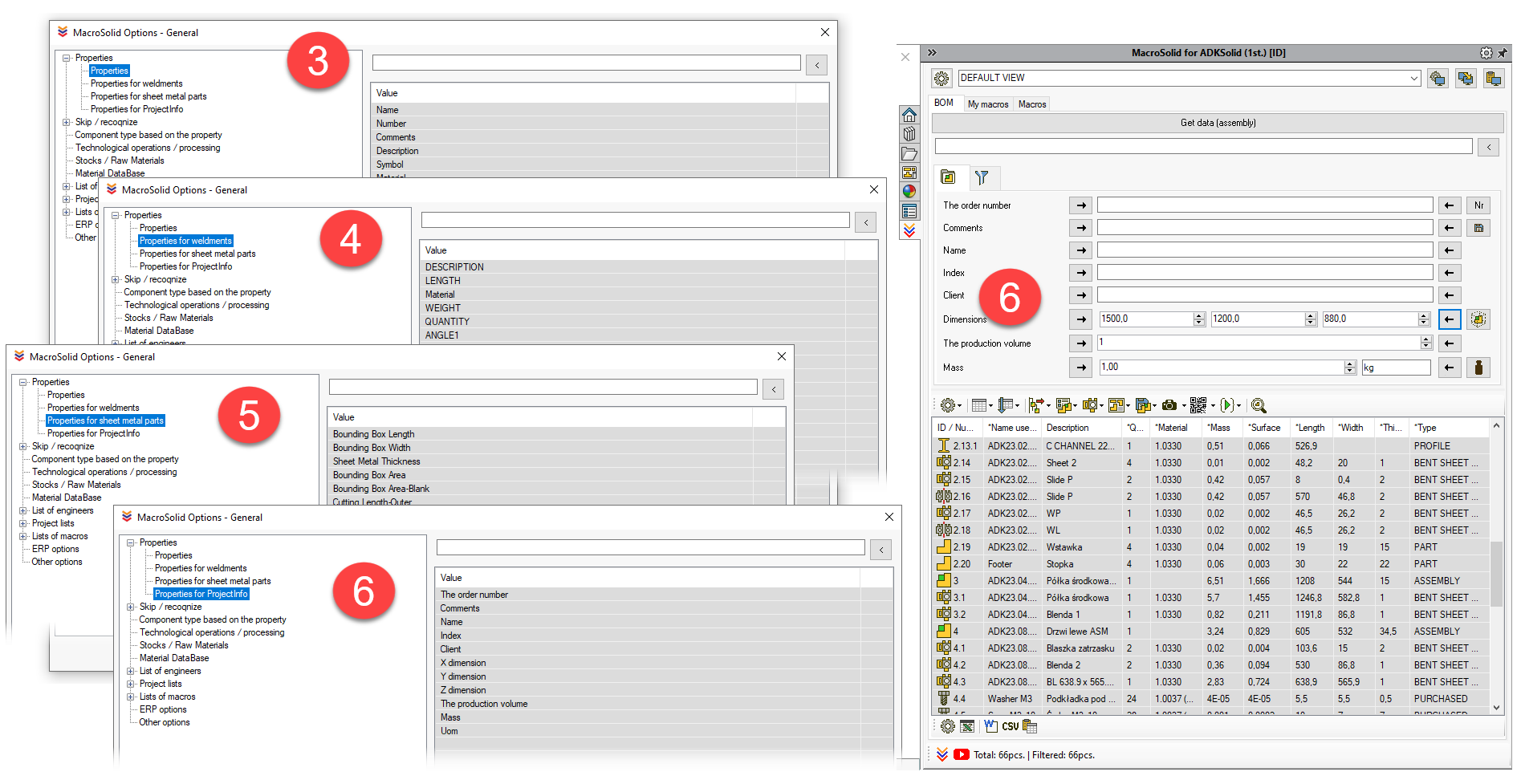
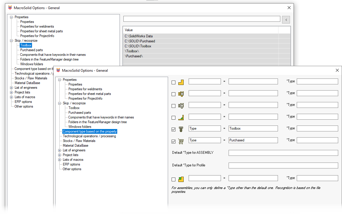
Managing Purchased Component Library
In General Options, specify paths for:
- standard parts,
- commercial components.
MacroSolid uses these paths to identify component types.
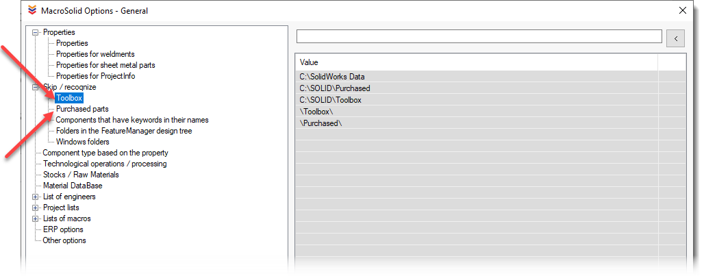
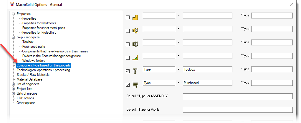
You can also define a file property to identify such components → go to the "Component type based on the property" tab.
🧰 Toolbox files are automatically recognized as standard parts.
First Launch – BOM Tab
We recommend starting with the BOM tab:
- Get data from the model.
- Filter components.
- Run selected macros.
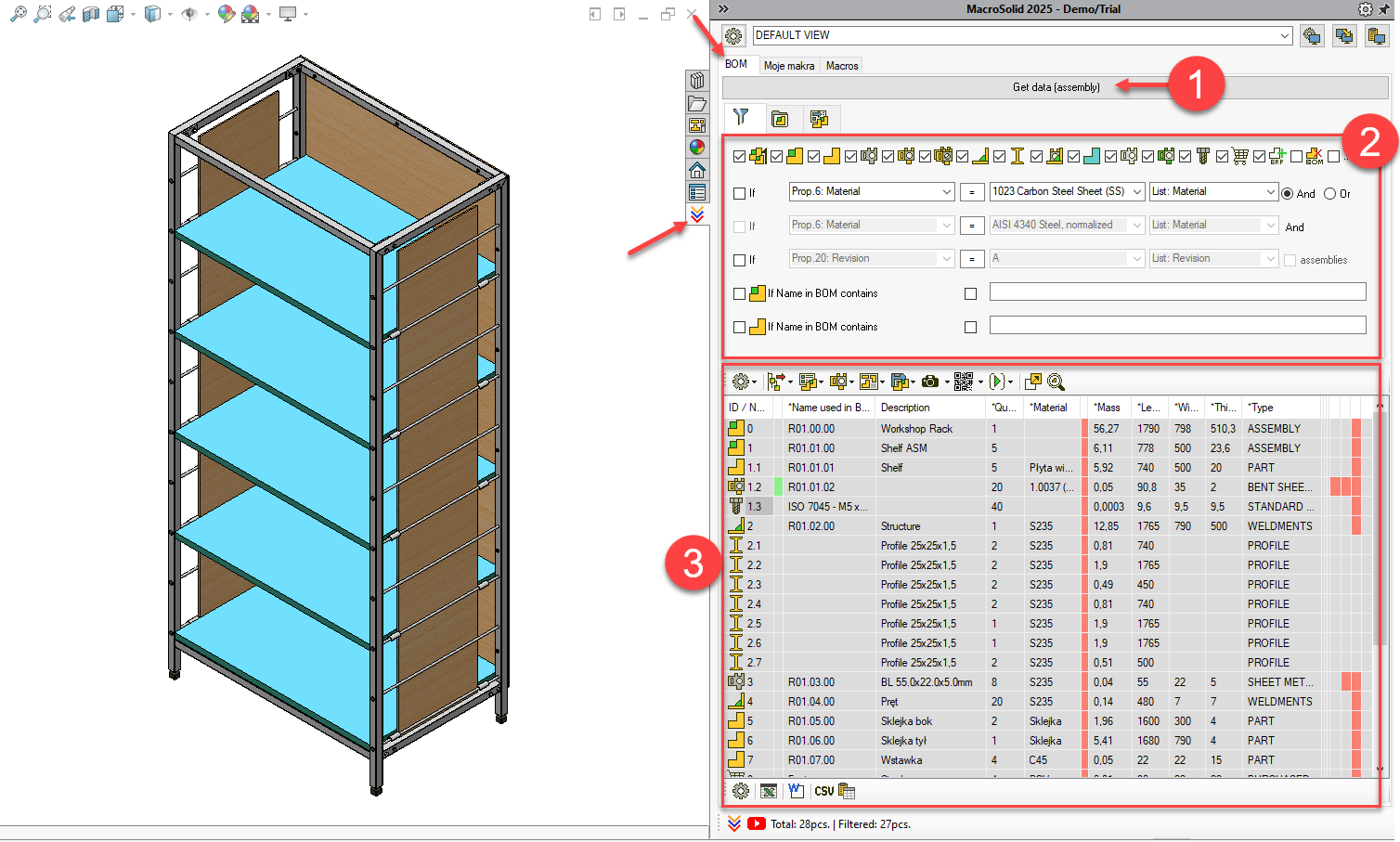
Go through filtering by component type. The BOM table will show only those that meet the criteria.
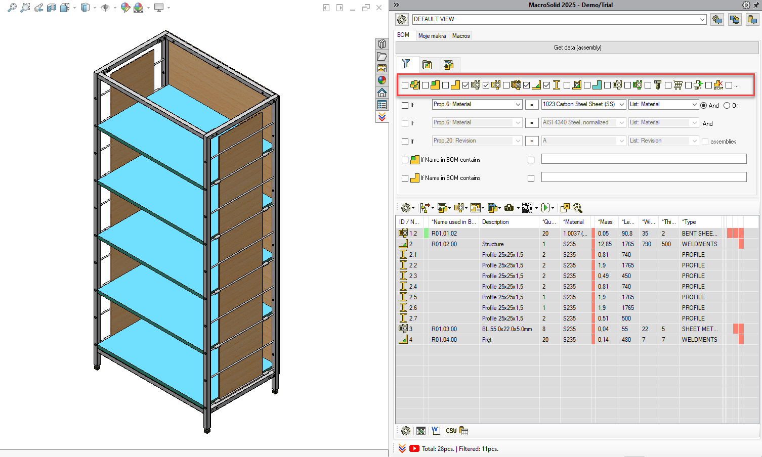
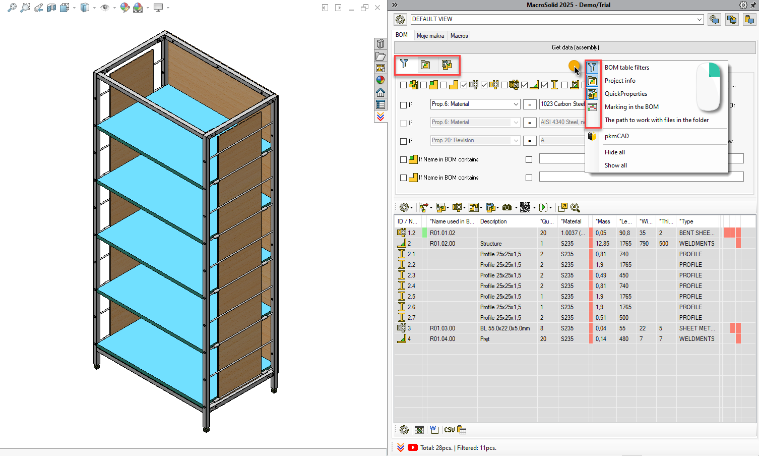
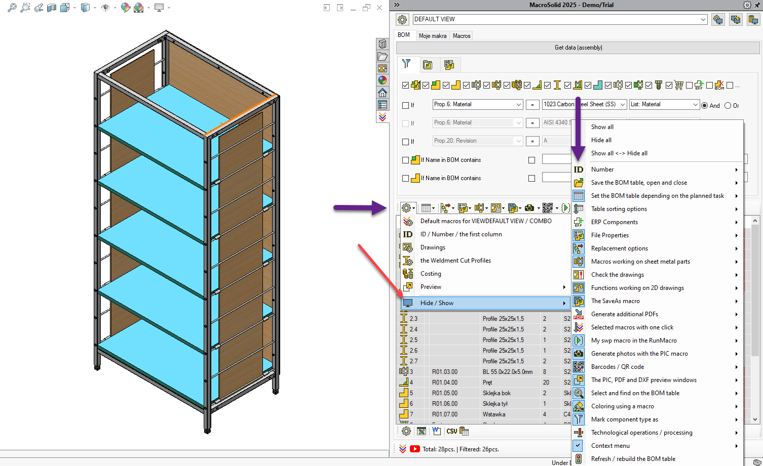
If you don’t see the filtering panel ![]() – right-click under the "Get data" button and enable the panel.
– right-click under the "Get data" button and enable the panel.
Customizing the BOM Table
At this stage, don’t make any changes to the BOM Table.
It is preset to provide immediate access to the most commonly used functions.
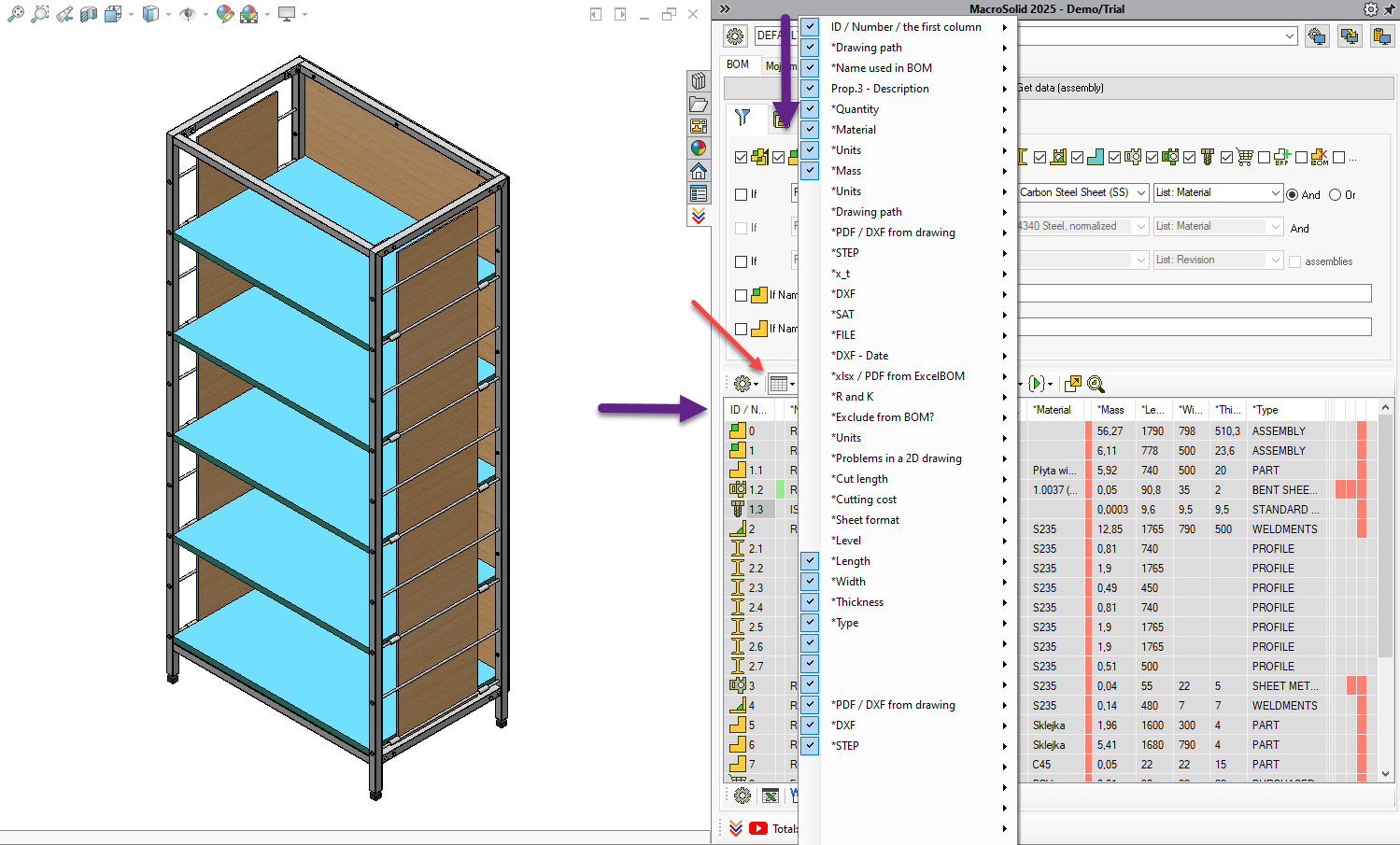
🔧 You can hide/show tools – but initially, do not change the configuration. 😉
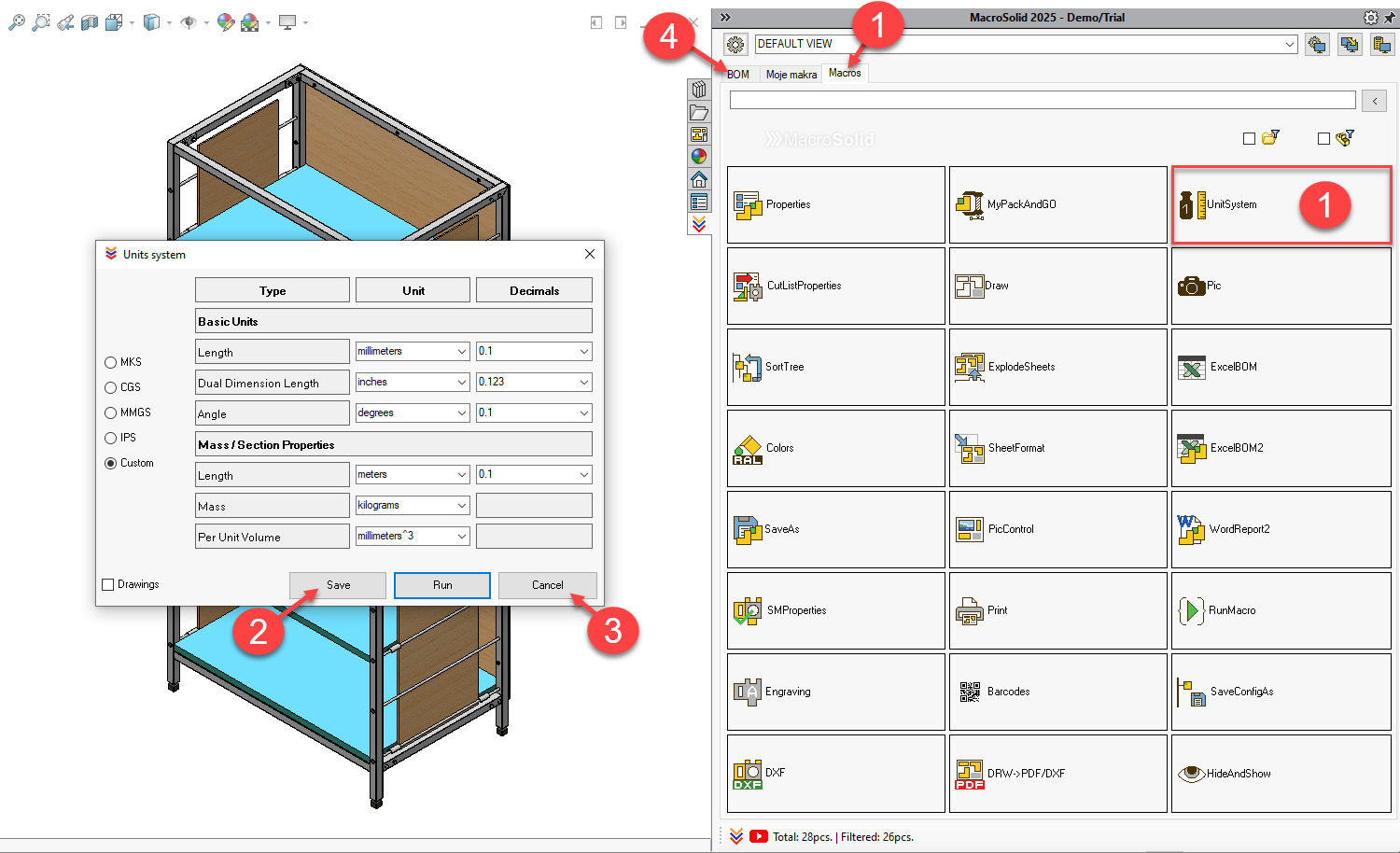
First Macro Launch – UnitsSystem 
- Go to the Macros tab and click UnitsSystem.
- Set the units, save, and
- click Cancel.
- Return to the BOM tab and get the data.
The BOM table will highlight components with units different than the set ones.
⚠️ Run the UnitsSystem macro from the button above the BOM table to unify units for all components or select rows and run it only for those – right-click → context menu.
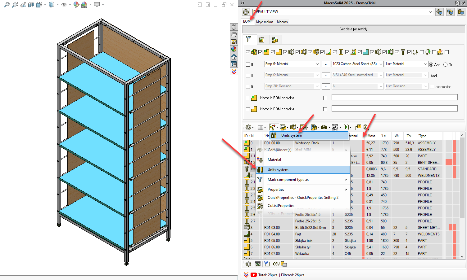
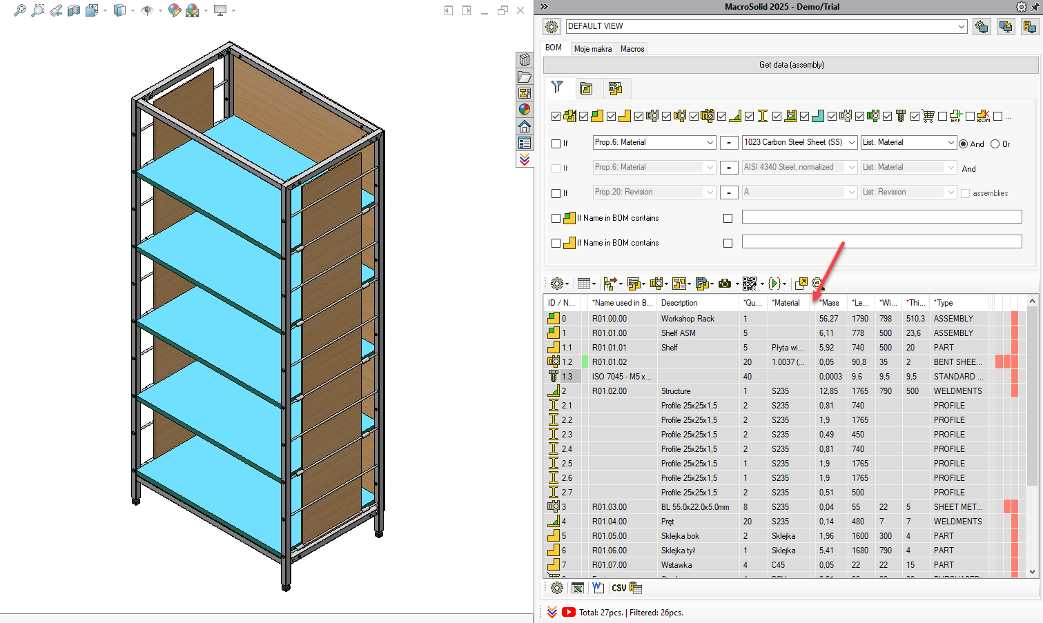
✅ The *Units and *Mass columns will be updated.
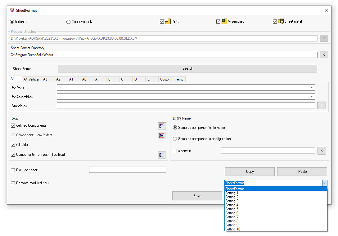
Generating PDFs from Drawings 
Click the PDF from Drawings button.
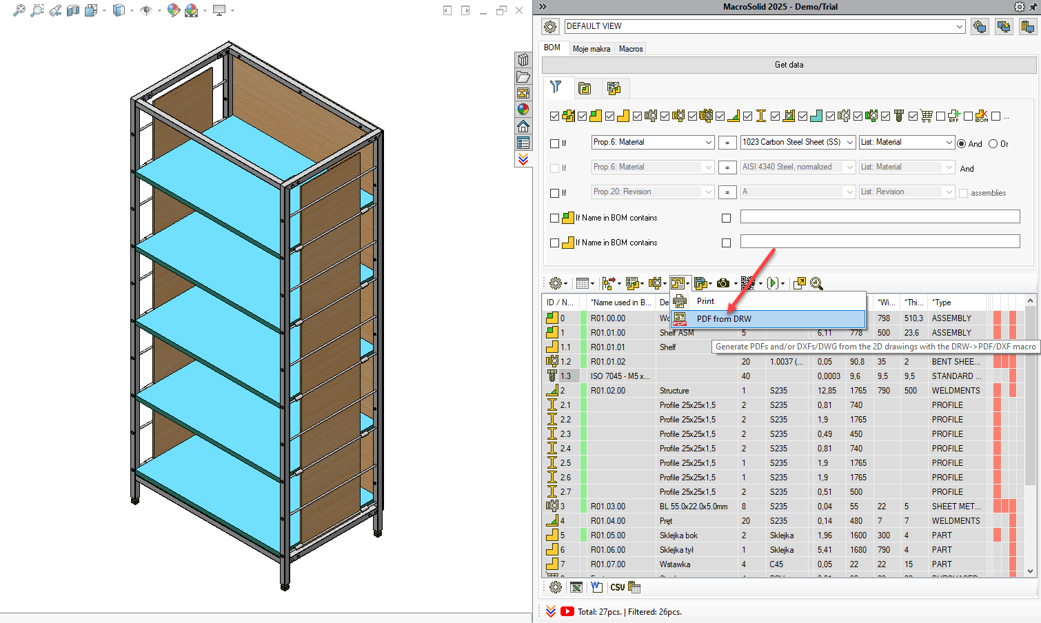
- PDFs will be saved in the /PDF folder at the assembly level.
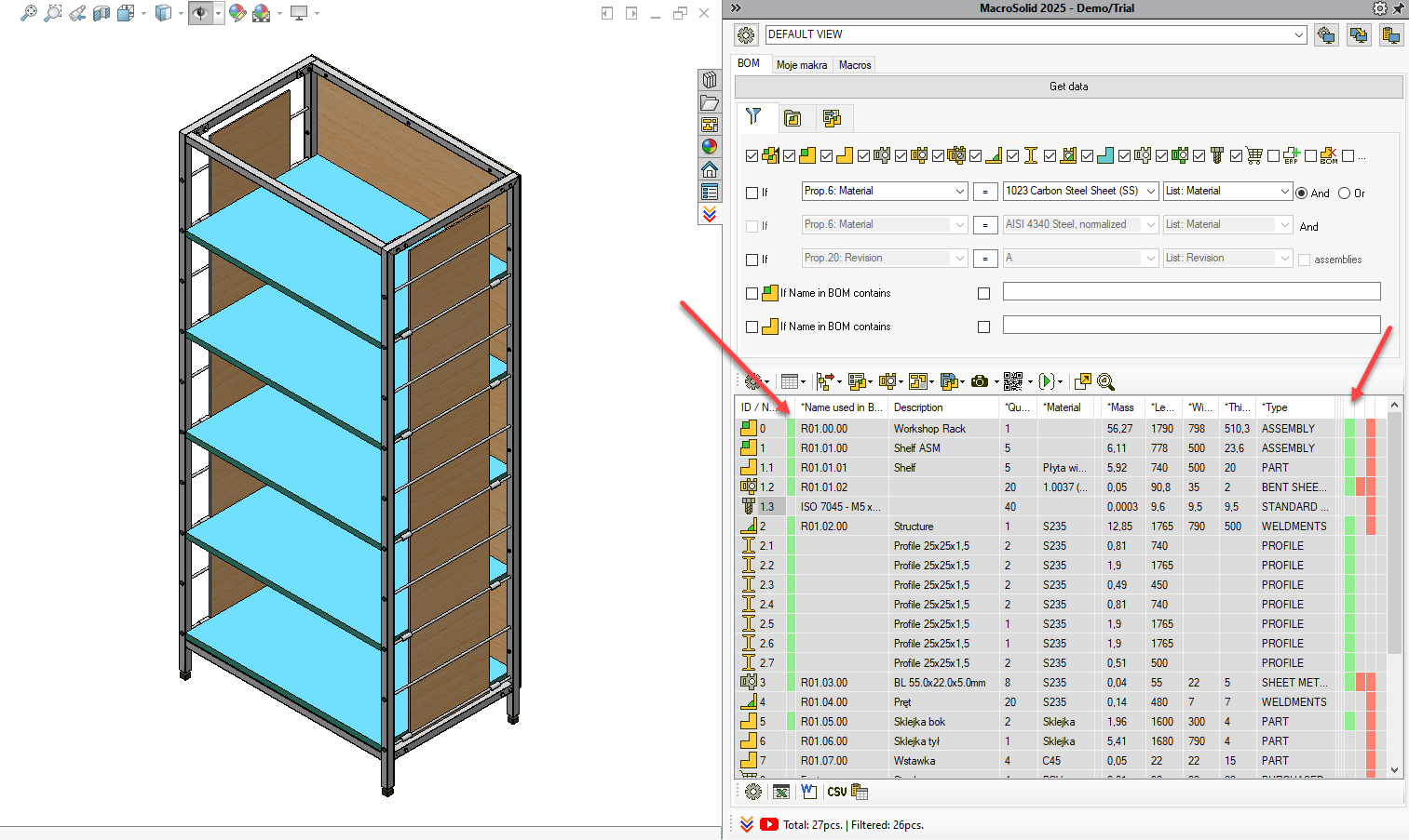
- The BOM table will show paths to both drawings and PDFs.
- Green = file exists, red = file missing.
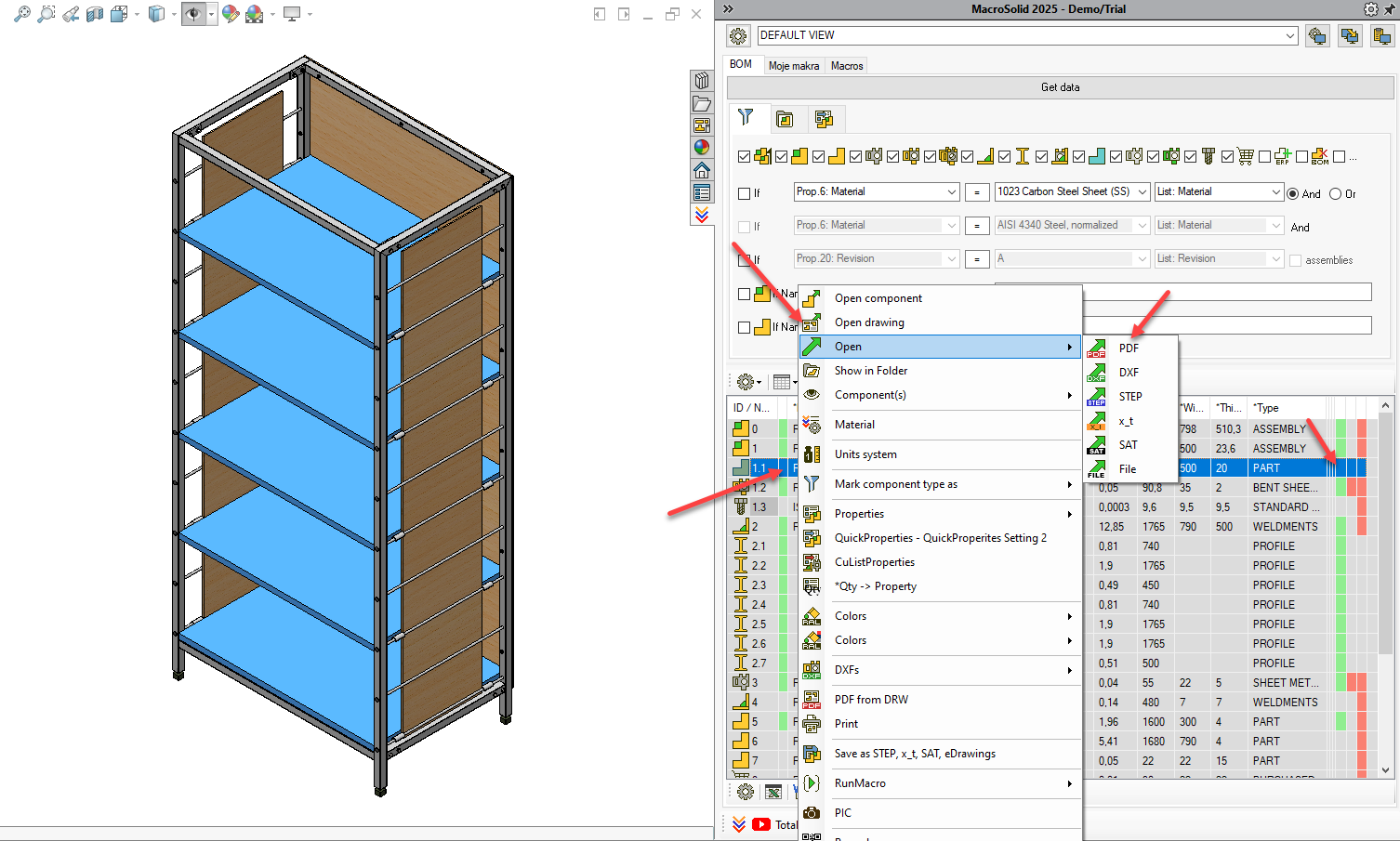
From the BOM Table, you can open drawings and PDFs (context menu or clicking on the cell in the path column).
Want to change SLDDRW to PDF conversion settings? Or generate DXF/DWG files along with PDFs? No problem.
- Go to the Macros tab and click DRW→PDF/DXF.
- Adjust the settings, save, and
- click Cancel.
- Return to the BOM tab and generate PDFs.
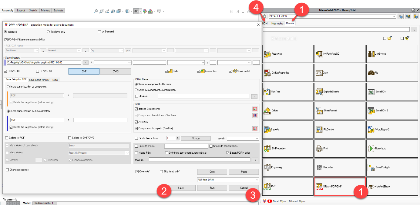
This process applies to all other MacroSolid functions – configure the macro, save settings → use in the BOM tab, in the BOM Table.
Generating DXF from Sheet Metal 
Same procedure – go to the DXF macro In the Macros tab, adjust settings, save and use from the BOM tab.
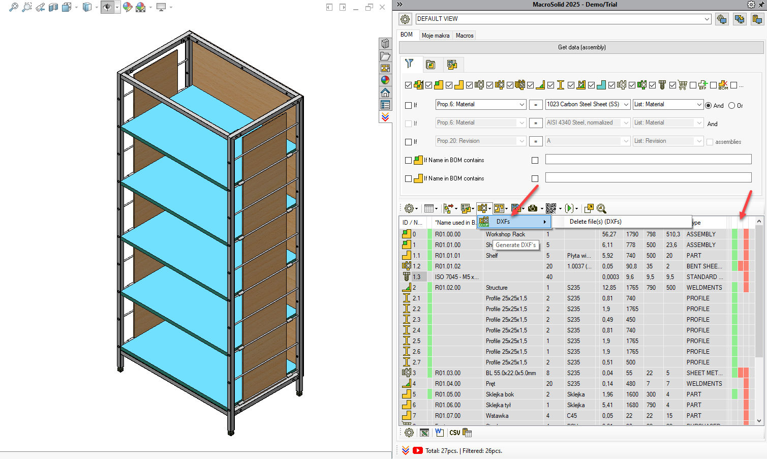
If you're using multibody modeling and your sheet metal parts might also be located within a weldment file, the procedure will be slightly different. The DXF macro can handle it. Let us know, and we’ll send you additional instructions.
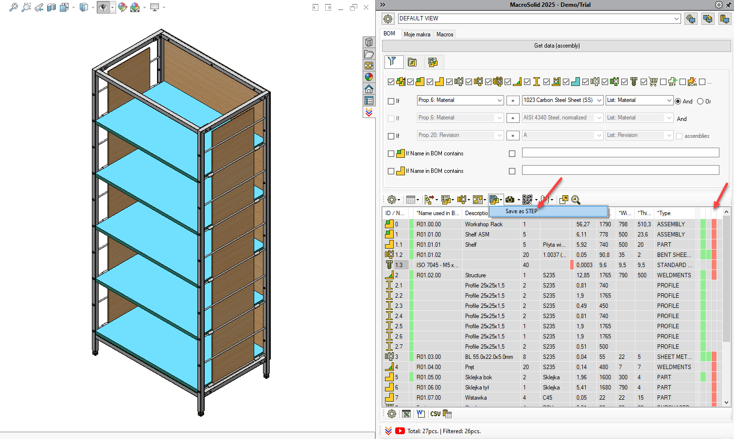
Generating STEP Files 
Same procedure – go to the SaveAs macro in the Macros tab, adjust settings, save and use from the BOM tab.
Changing Properties  –> Example 1
- Go to the QuickProperties tab.
- Fill in the constructor list in MacroSolid’s general options.
- Choose the "assign from list" function: List: DrawBy, List: CheckedBy, List: ApprovedBy.
- Assign a constructor from the list you defined.
- Run QuickProperties – PROJECT TEAM for all in the table or select components with CTRL or SHIFT and run it from the context menu (right-click).
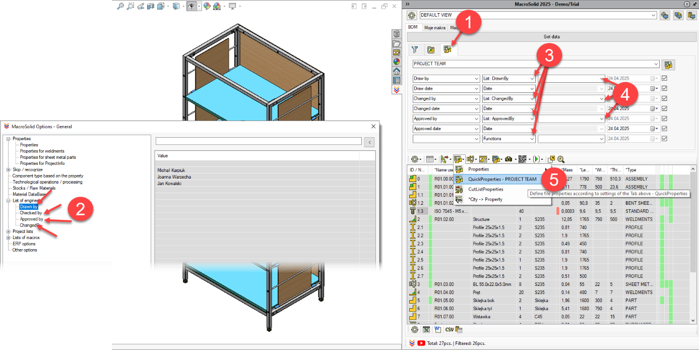
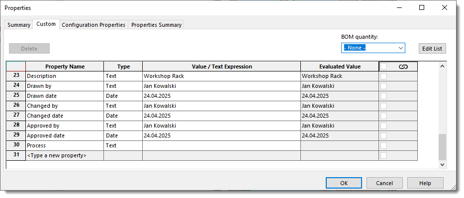
You’ve now filled in customized properties specific to your configuration.
Changing Properties –> Example 2
- Go to the QuickProperties tab.
- Choose REVISION setting.
- Select value A from the list.
- Run QuickProperties – REVISION for all in the table.
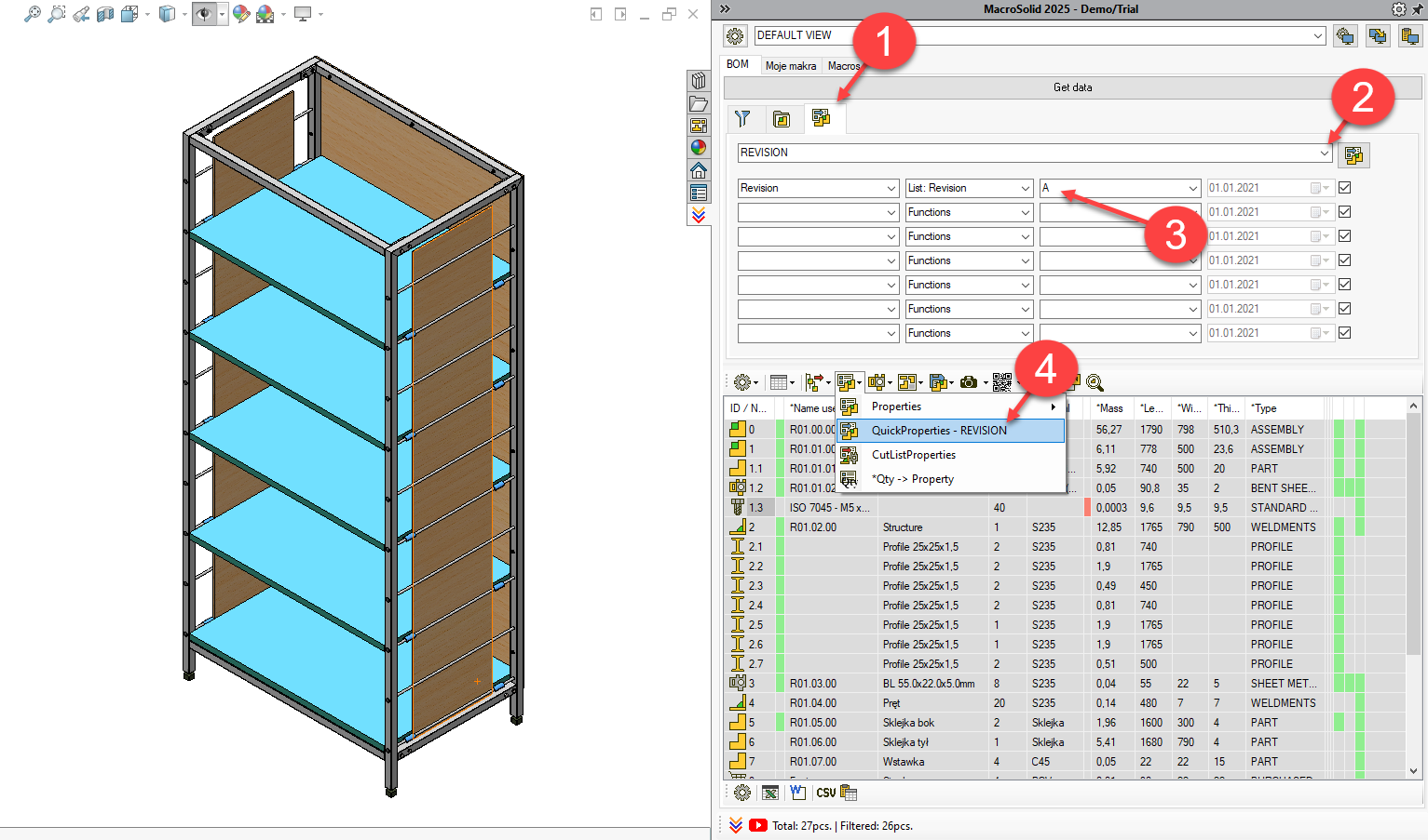
You’ve just set Revision = A for all visible in the BOM Table. - Select value B.
- Select two or three rows using CTRL and right-click to run QuickProperties – REVISION from the context menu.
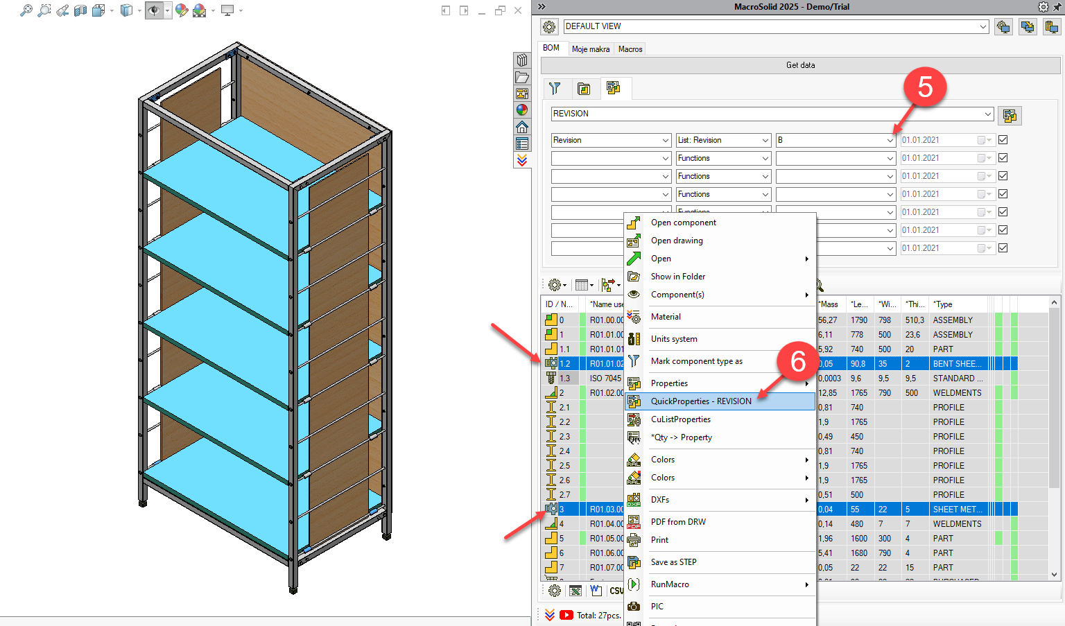
You’ve now set Revision = B for those selected rows.
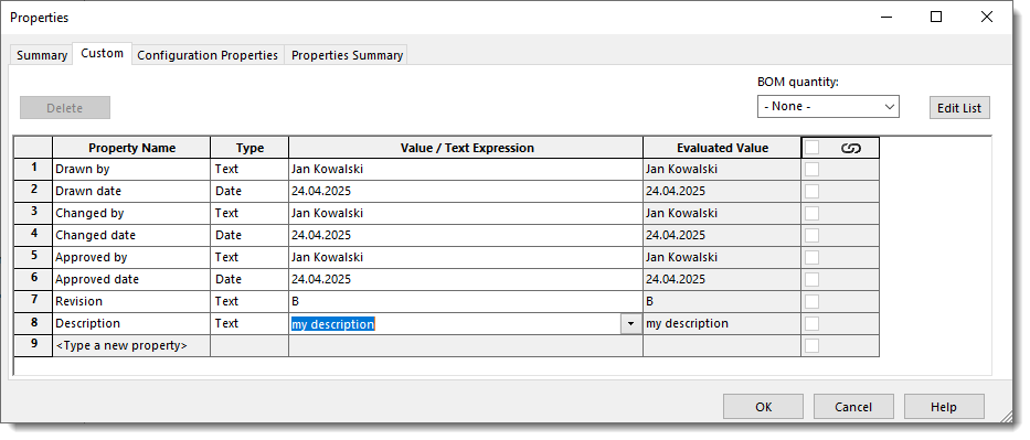
Changing Properties –> Example 3
- Click the Description column cell with the left mouse button.
- Enter the description and click anywhere in the table. Enter key won’t work ☹
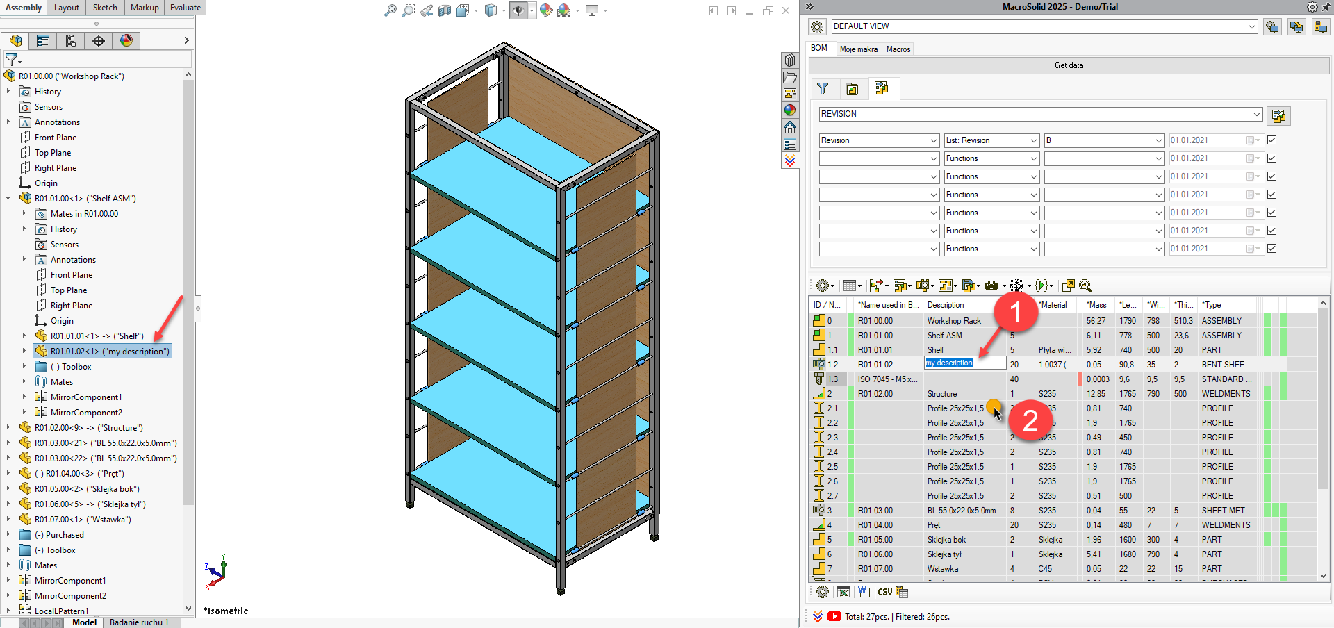
You’ve just set the Description property.
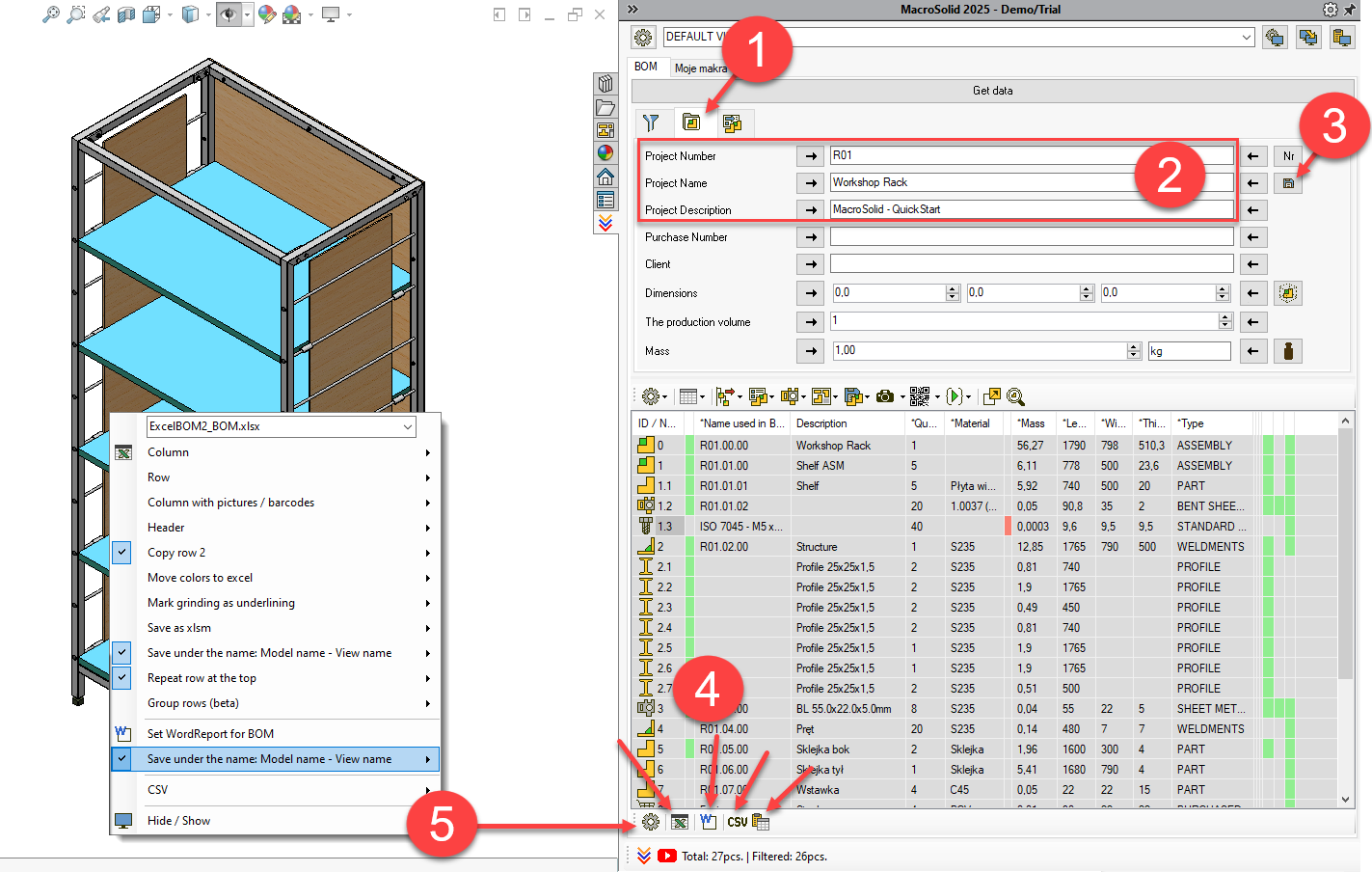
Bill of Materials, Report, Summary
To wrap up this initial MacroSolid walkthrough, generate your first BOM list to .xlsx, a report to .docx.
- Go to the ProjectInfo tab.
- Enter: Project Number, Project Name, Project Description.
- Save the data → this assigns the data to the active document’s properties.
- Export to: MS Excel (.xlsx), MS Word (.docx), CSV, or copy the BOM Table to clipboard.
- To access BOM export settings, click the gear icon.
MacroSolid - Pic
Macro PIC is a component photo generator. By default, .png files are saved in the "Pic" folder of the same location as the component from which the photo is generated, but in the macro settings you can plan the name and define the target saving path. These photos are used by MacroSolid functionalities, e.g., in MS Excel® or MS Word® reports. Related to the PIC macro is the functionality of Delete PIC photos or folders, and of hiding items in the graphics area that may cause incorrect "Fit to Screen". You can check in the *Pic column whether the photos have been generated... READ MORE
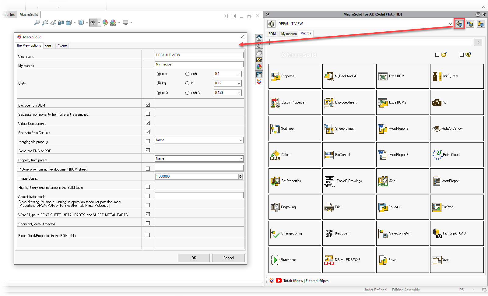
MacroSolid configuration
MacroSolid has been designed so that everyone can use all the functionalities, regardless of the SOLIDWORKS® version, adopted settings and defined file properties. Each macro is developed in the scope of one specific functionality, hence some windows with settings to be configured may seem extensive.
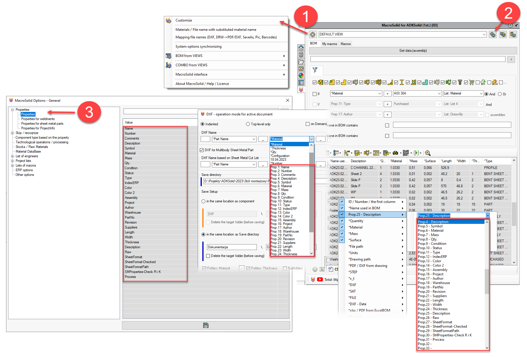
MacroSolid has global settings (1) and those assigned to the view (2). Settings assigned to a view must be defined each time at the level of the active view.
First of all, it is necessary to define a list of properties (3) used when creating technical documentation, check and possibly supplement it with additional properties of cut elements assigned to objects that are profiles (4) and those that represent sheet metal (5). The names of custom and configuration-specific properties are especially important because they can be referenced in many of the add-in's functionalities. The ProjectInfo properties are those that are supported by the tab for defining general project data.
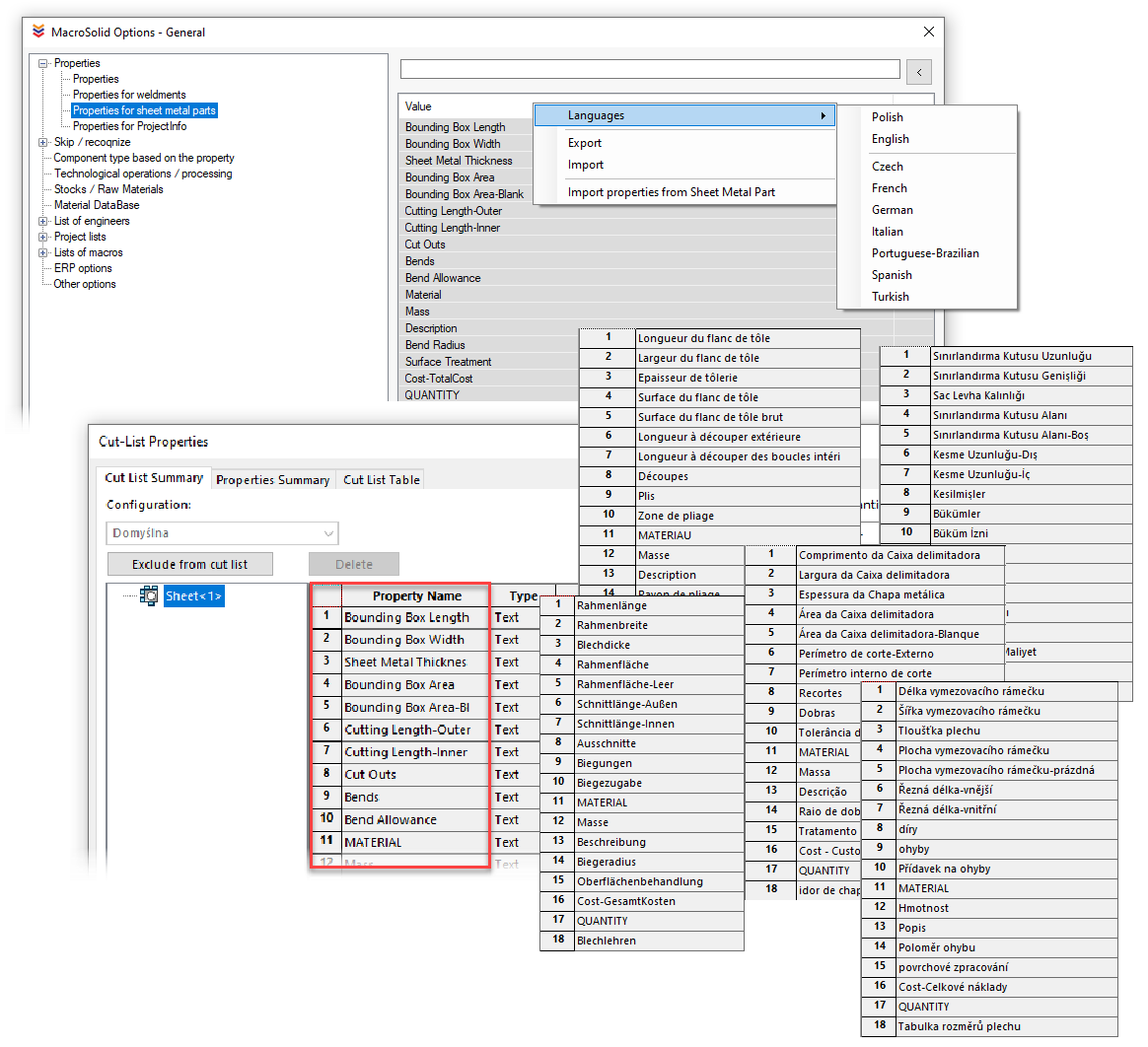
ATTENTION!!! Depending on the language version, SOLIDWORKS® generates different names for the properties of cut sheet metal and welded structures. Their synchronization is required for the correct operation of the MacroSolid add-in. In the list with property names, right click on the context menu and select your language.
Paths to the library with standardized and commercial models are to be defined in the main settings configurator, as on this basis, such elements are recognized by MacroSolid. Commercial components can also be identified through the file properties - the "Component type based on properties" tab.
Macros run from the dialog box can skip components that contain specific phrases listed in the "Components" list and those components that are in the folders of the FeatureManager tree. Folder names are defined on a dedicated list. These types of components can also be filtered in the MacroSolid BOM table.
MacroSolid supports functionalities related to manufacturing technology. In the general options, it is possible to define the names and values of technological operations and machines, their marking settings as well as settings for semi-finished products.
In MacroSolid you will also find functionalities for fast defining and replacing materials. However, they require entering the path to the sldmat material libraries used in the company.
Engineers` lists, project and macros are used primarily by the macro to define file properties, i.e., the Properties macro. In the BOM tab, these lists can be used to set up quick filtering.
Options related to integration with other systems have been placed in the "ERP Options" tab, options related to the general behavior of the add-in in the "Other Options" tab.
The global settings also include the settings of individual macros, because once configured functionality can be run in different modes: without loading the macro settings window and from the BOM tab on the entire table as well as selected ones. We made it possible to save and load several settings within one macro, so you can store your settings and swiftly switch between them.
In addition to global settings, we have settings assigned to VIEWS - from the name of the view, the name of the "My macros" tab, through the options for getting data from the model, to other less significant ones that allow you to adjust the operation of individual functionalities within the active VIEW, and not the entire MacroSolid add-in.
Copyright © ADKSolid. All rights reserved
MacroSolid - Barcodes
Barcodes is a barcode generator integrated with SOLIDWORKS®. The macro allows you to generate linear and 2D barcodes.
1D: Codabar, Code 11, Code 2 of 5, Code 39, Code 93, Code 128, EAN 8, EAN 13, GS1-128 / EAN-128, Interleaved 2 of 5, ITF-14, MSI Plessey, USPS OneCode, PLANET, POSTNET, RM4SCC, UPC-A, UPC-E.
2D: Data Matrix, PDF 417, QR Code
Graphic files with codes can be saved with the planned name in the "Barcodes" folder next to the component file or in the indicated folder. You choose the type of code, define its size, but also the dimensions of the png file. For QR codes, you will configure the size, correction and version... READ MORE
MacroSolid - ImageQuality
ImageQuality allows you to control and define the image quality of documents by: selecting its value, maximum or minimum value, or by percentage position of the TrackBar slider. The *Image Quality column in the BOM tab will display the current image quality value and will be colored green, orange, and red depending on how close it is to a value that significantly increases file size, slows down graphics performance, and increases memory consumption... READ MORE