


MacroSolid - STEP by STEP
If you have completed the QUICK START guide, you’re ready to take your MacroSolid skills to the next level.
In the default configuration, we have prepared several VIEWS — interface layouts designed to support specific tasks related to automating your work in SOLIDWORKS®. These VIEWS are arranged in a logical order to make your work easier and help you achieve maximum efficiency.
By following this step-by-step guide, you will discover the full potential of MacroSolid and learn how to use its features effectively.
VIEW 1 – COMPONENT TYPE – Check, Tag, Sort
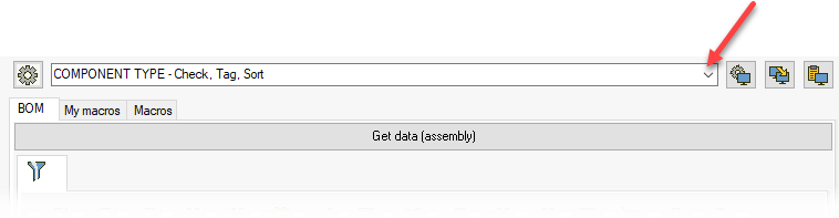
Go to VIEW: COMPONENT TYPE – Check, Tag, Sort
The first VIEW is designed to help you verify whether your company’s SOLIDWORKS® modeling standards have been applied correctly.
The BOM table displays all components according to the SOLIDWORKS® FeatureManager tree — preserving both the order and nesting structure. The first column uses icons to indicate the component type — sheet metal (with or without bends), multi-body sheet metal, clean weldments with their profiles, or weldments containing both sheet metal and solid bodies. MacroSolid also identifies standard assemblies, parts, and purchased components, distinguishing between standard (normalized) parts and other purchased items.
The BOM table shows columns for file names, component descriptions, and additional columns:
- *Exclude from BOM? — shows whether a component is excluded from the bill of materials (BOM),
- *Folder name,
- *PIC — displays a preview path (PNG file),
- *Type — the type detected by MacroSolid,
- Type (without asterisk) — the value from the component’s property.
-
Download data from the model
Click Get data to load component information.
-
Run the PIC macro
This generates preview images for the components.
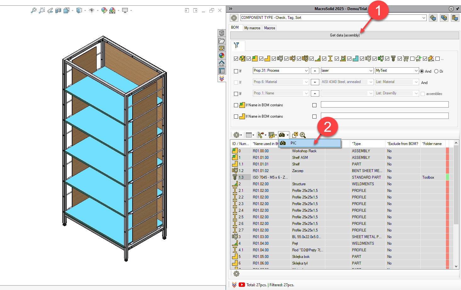
-
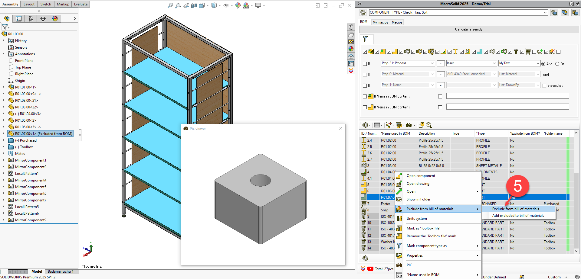
Enable PIC preview
Adjust and position the preview window as needed.
When you select a row in the BOM table, the generated image of that component will be displayed.
-
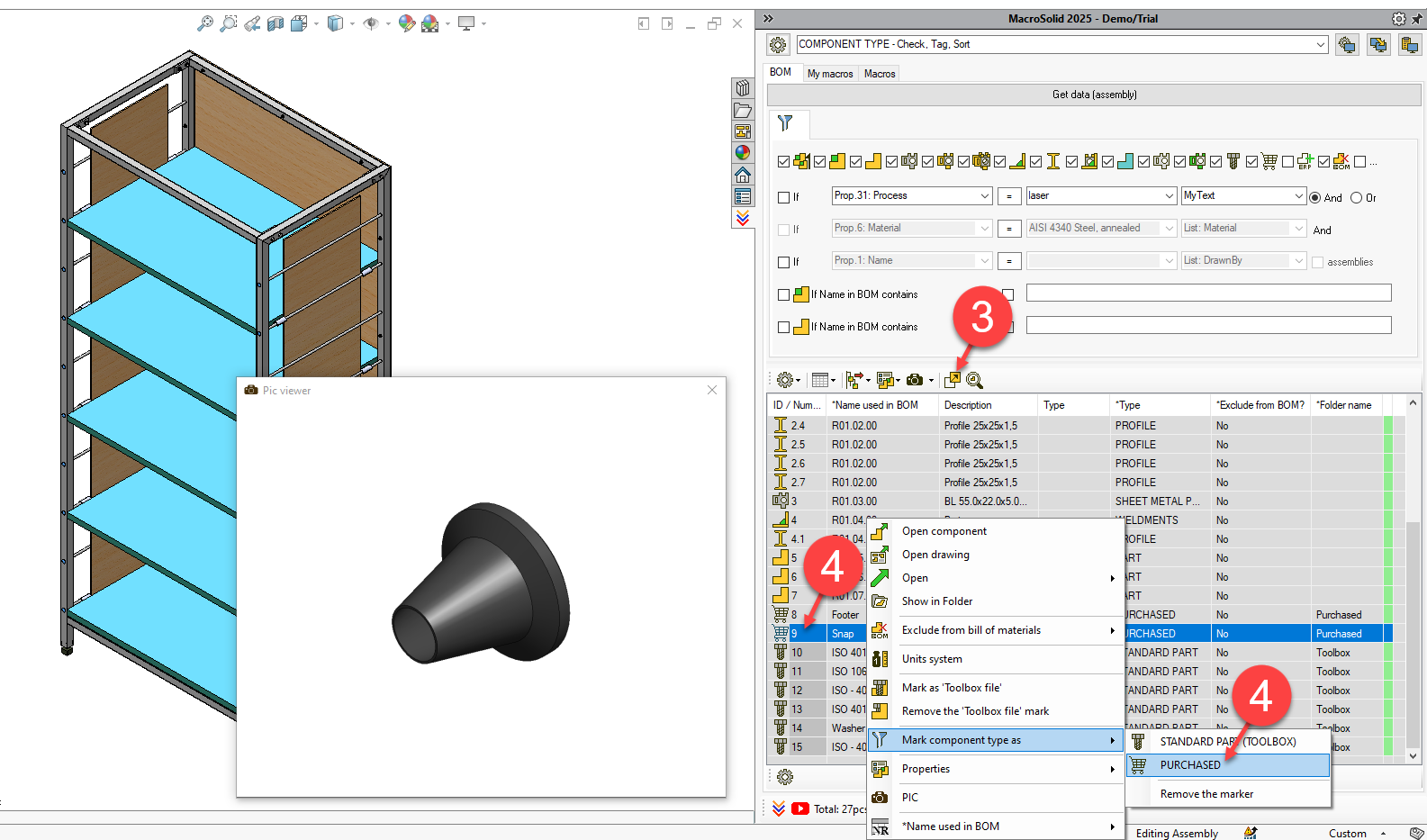
Check recognition of standard and purchased components.
- Browse through the table rows.
- If the first column is missing the bolt or cart icon, the file wasn’t recognized as a purchased component.
In that case:
- Check if the file is in the correct purchase database folder (see the QUICK START guide).
- Or right-click the row and select: Mark component type as.
-
Verify excluded components
For any component that shouldn’t be included in the BOM, right-click and select: Exclude from bill of materials.
-
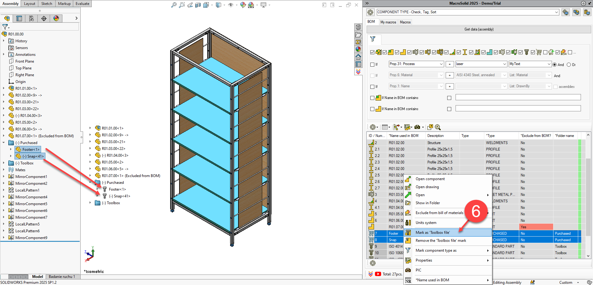
Tag files as Toolbox components (optional)
If you want files to be recognized by SOLIDWORKS® as Toolbox library parts, use the function: Mark as ‘Toolbox file’.
⚠️ Note: The Toolbox icon will appear after reopening the model.
-
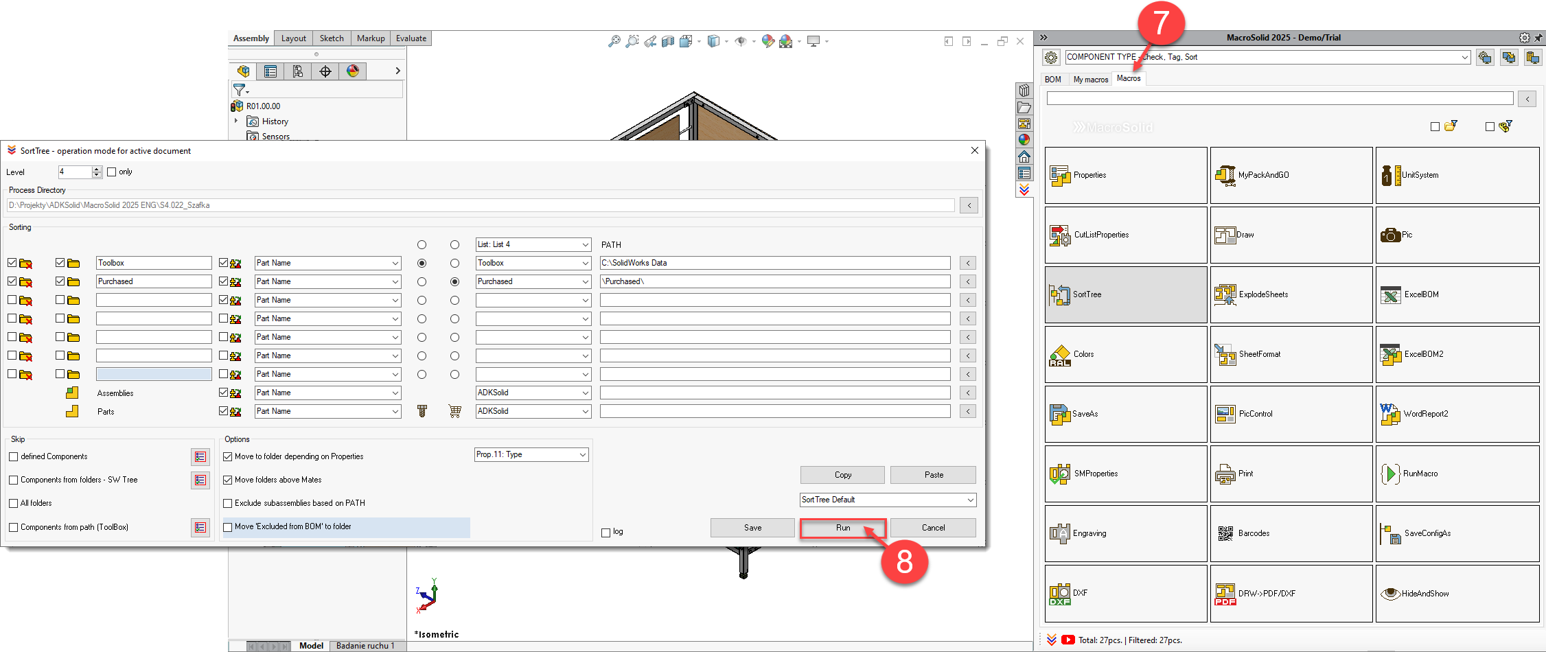
Go to the Macros tab.
-
Run the SortTree macro
This will organize the FeatureManager tree.
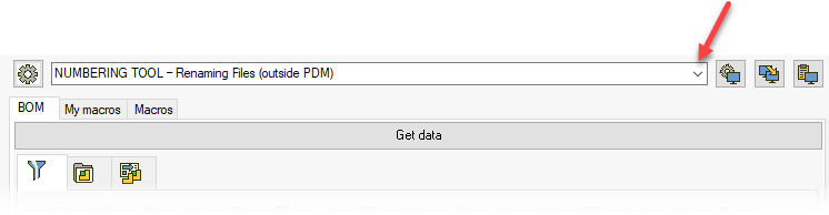
VIEW 2 – NUMBERING TOOL – Renaming Files (Outside PDM)
Go to VIEW: NUMBERING TOOL – Renaming Files (Outside PDM)
In an ideal design process, engineers don’t need to manually name files — names are generated automatically, following the company’s numbering scheme.
In practice, however, during modeling, changes often occur: components are added or removed, and the order and structure of assemblies may change. That’s why proper file names should be assigned at the right stage — once the project structure has stabilized.
-
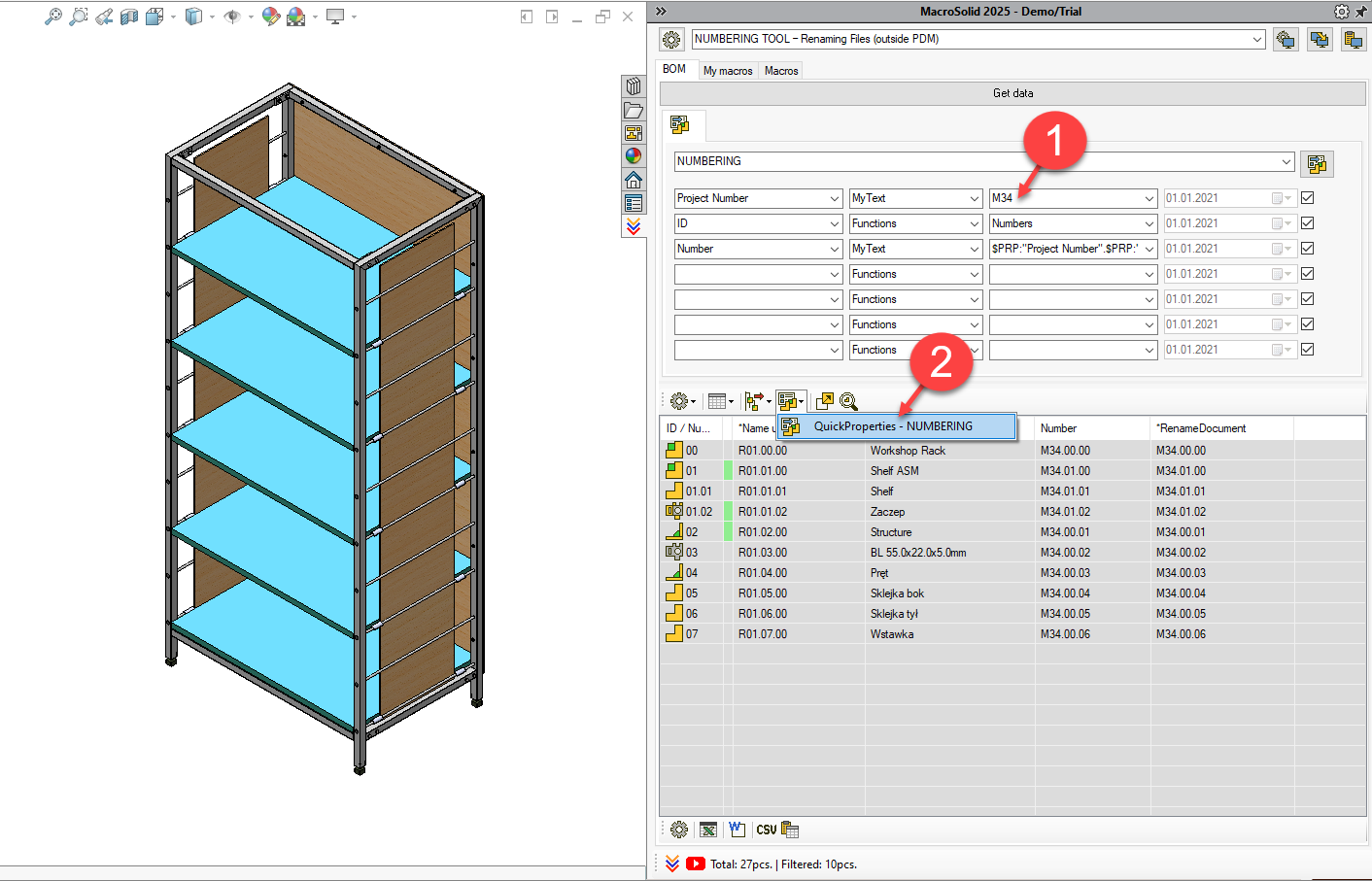
Enter the project number
This number will be used as a prefix in the file naming scheme.
-
Run the QuickProperties – NUMBERING macro
This macro generates sequential numbers for assemblies and parts based on the defined scheme.
-
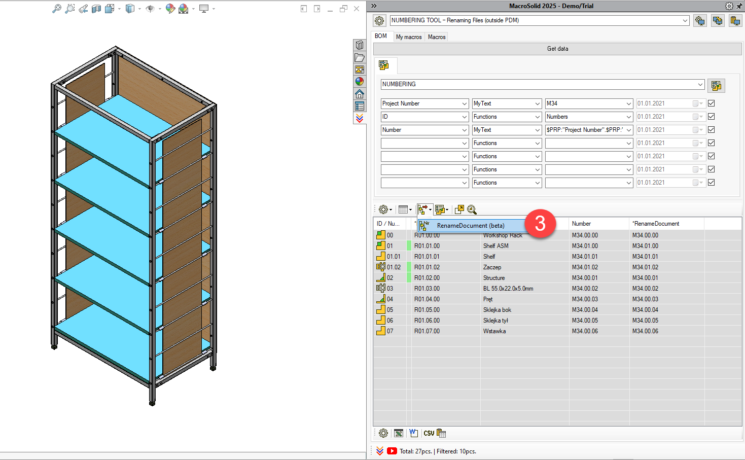
Check the *RenameDocument column in the table
If none of the cells are marked red, you can safely proceed with renaming the files in the active model.
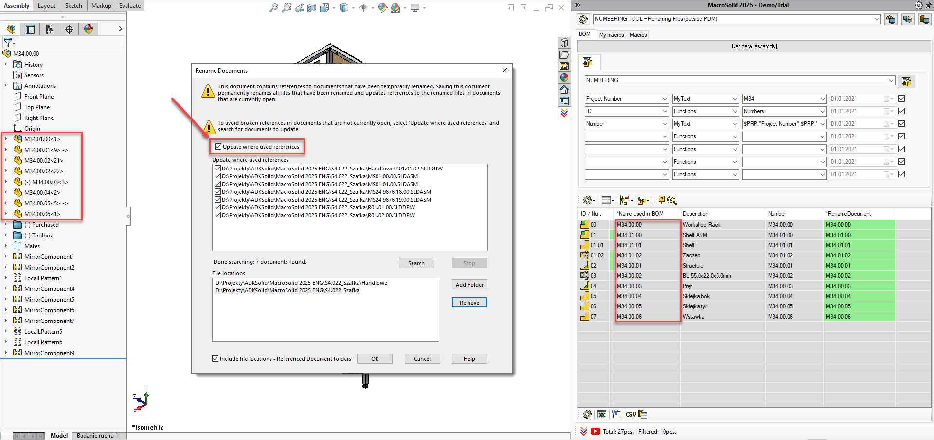
⚠️Warning: The renaming process is irreversible. Make sure everything has been thoroughly verified before proceeding.
⚠️Important: When saving the model, a SOLIDWORKS® dialog box will appear. Select the option:
Update where used references — this ensures correct links to existing drawings.
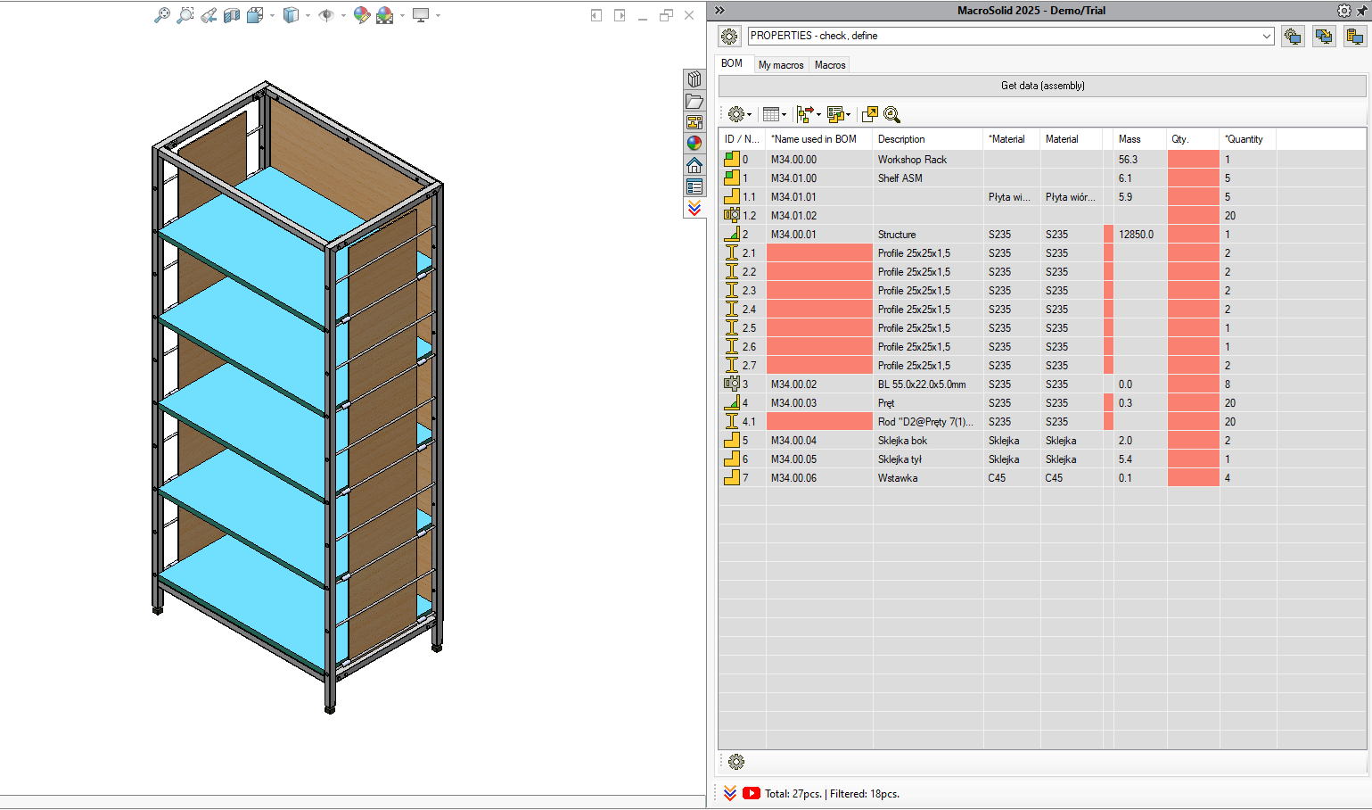
VIEW 3 – PROPERTIES – check, define
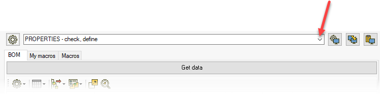
Go to VIEW: PROPERTIES – check, define
This VIEW is designed to present a summary of key data filled out in the SOLIDWORKS® properties tab or in the PDM system — these are the same details that appear on 2D drawings and in bills of materials (BOM).
Rule: If a value is missing in the BOM table, it won’t appear on the drawing either.
-
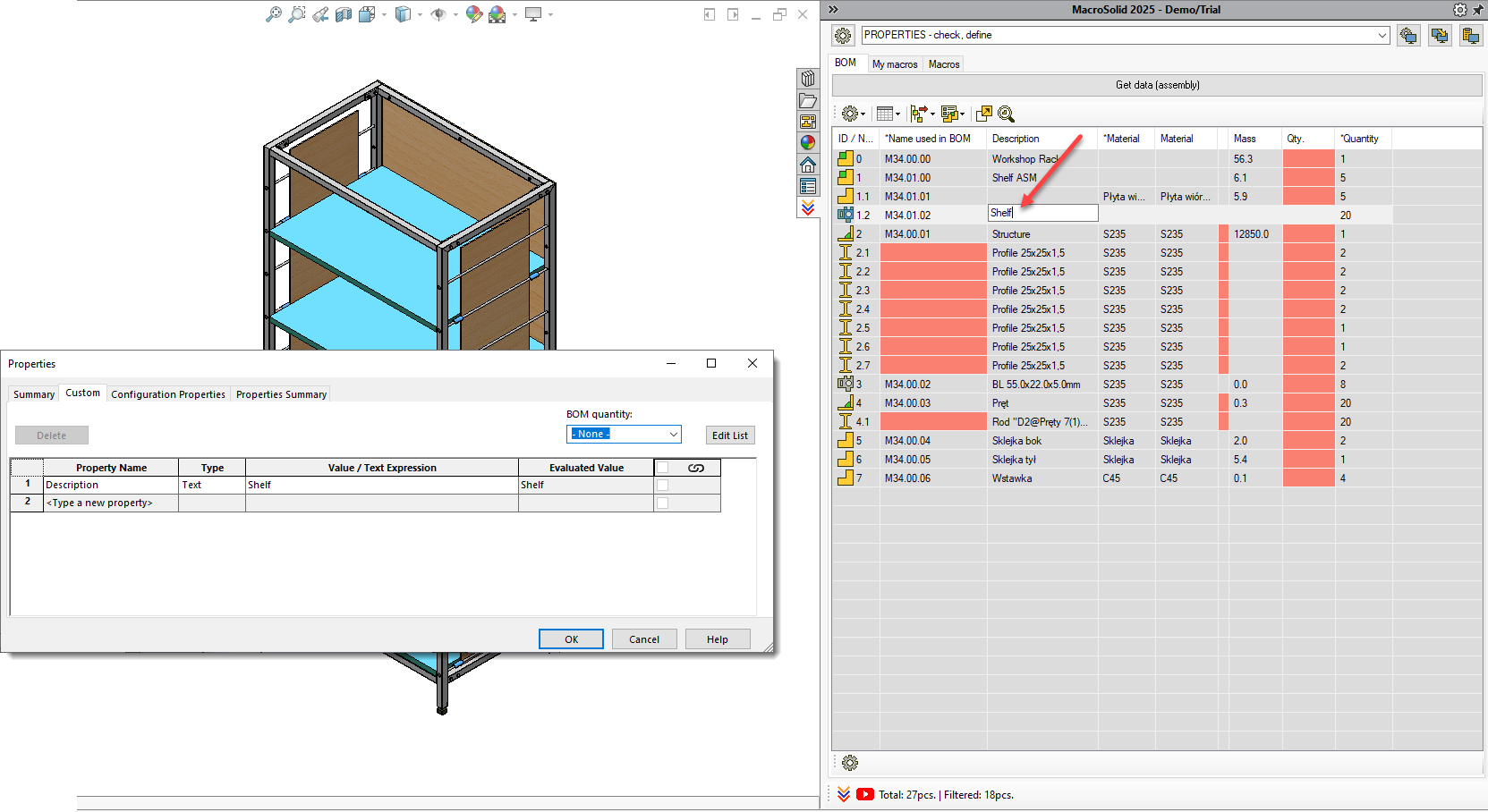
Fill in the description (Description)
Double-click a cell in the Description column and enter a description for each component. The description is saved as both a custom and configuration-specific property.
⚠️ Note: For weldment profiles, the description is pulled from the cut list item and is read-only — you can’t edit it manually.
-
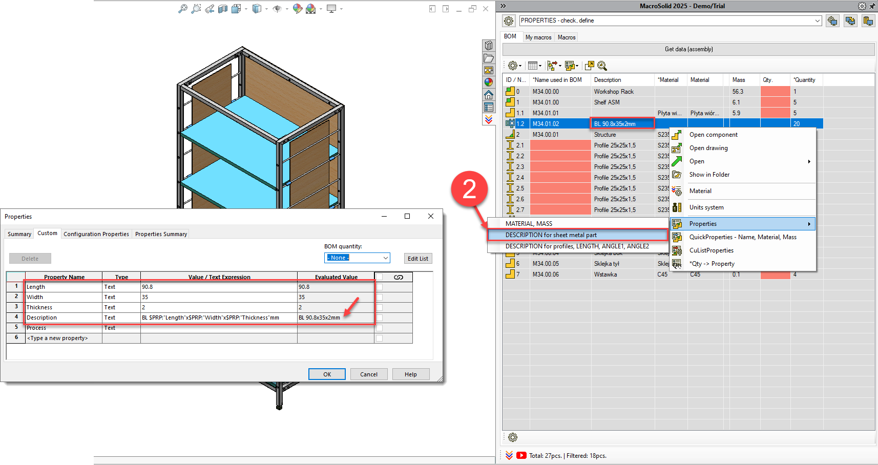
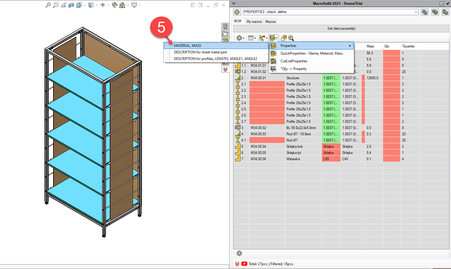
Automatic description for single-body sheet metal parts
- Select sheet metal parts in the BOM table (hold CTRL).
- Right-click and choose: DESCRIPTION for sheet metal part.
- The Properties macro will automatically fill in the relevant properties.
-
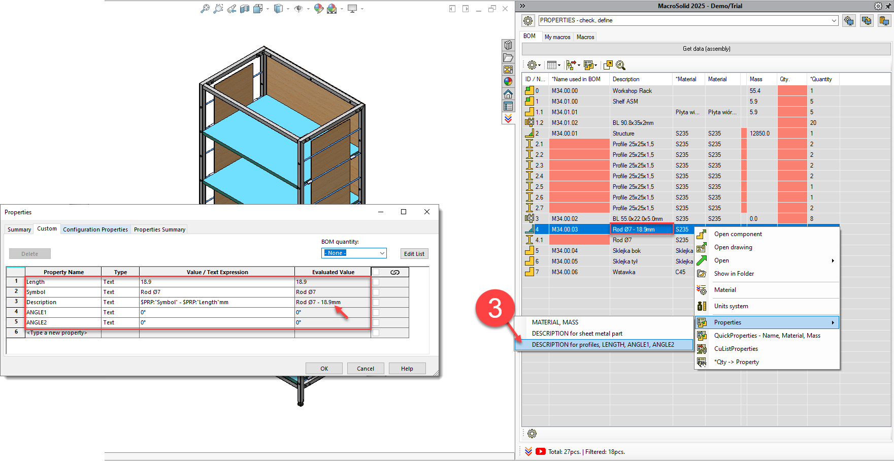
Automatic description for single-body profiles
- Select single-body profiles (with CTRL).
- Right-click and choose: DESCRIPTION for profiles, LENGTH, ANGLE1, ANGLE2.
-
Assigning material
- The *Material column shows the material defined in the model.
- To set or change it:
- Right-click and select Material.
- Choose the material from the database and click Apply and Close.
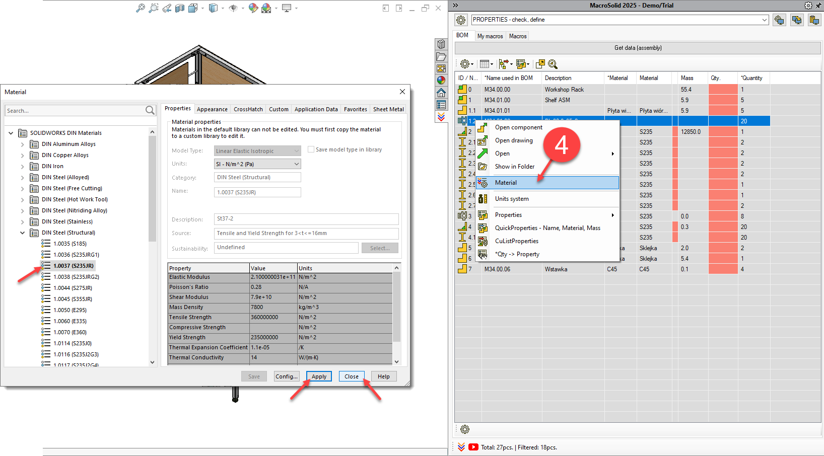
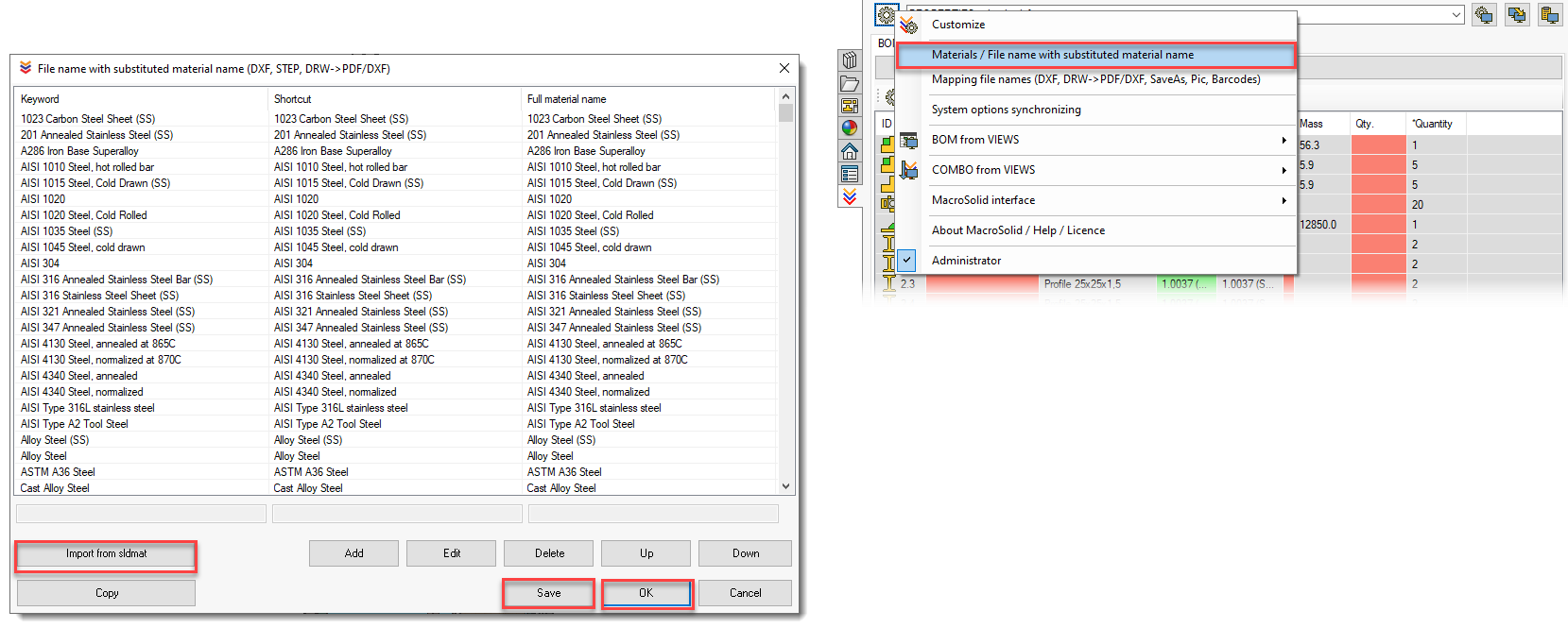
📌 Info: If the material is not found in the MacroSolid library, the *Material cell will be highlighted. You can import your own .sldmat library.
-
Material and Mass columns
These display the property values.
To update them for all components, run the macro: Properties – MATERIAL, MASS.
-
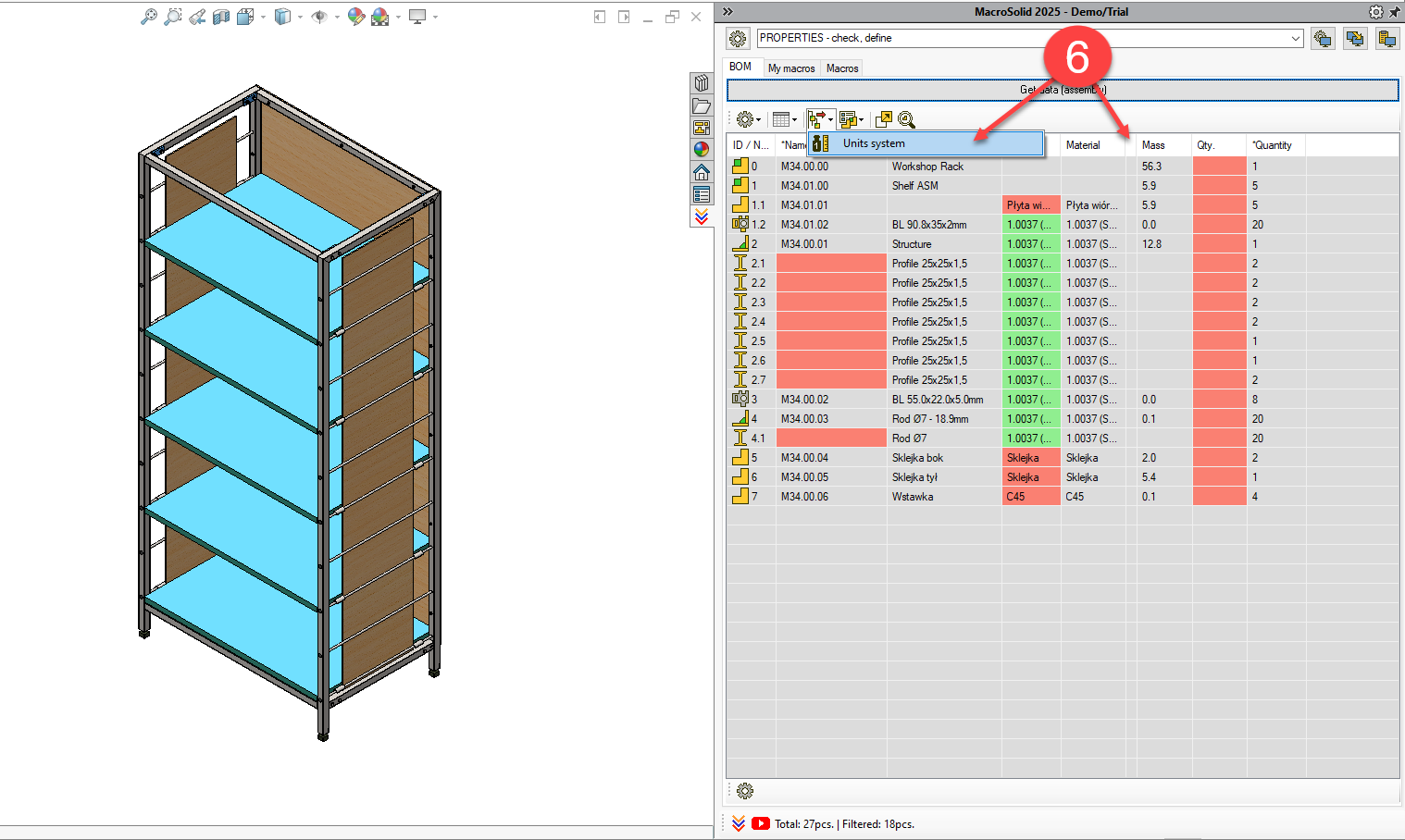
Unit consistency
- If *Units column is highlighted red, it means the units don’t match the settings of the UnitSystems
- Run UnitSystems to unify mass, length, and angle units.
-
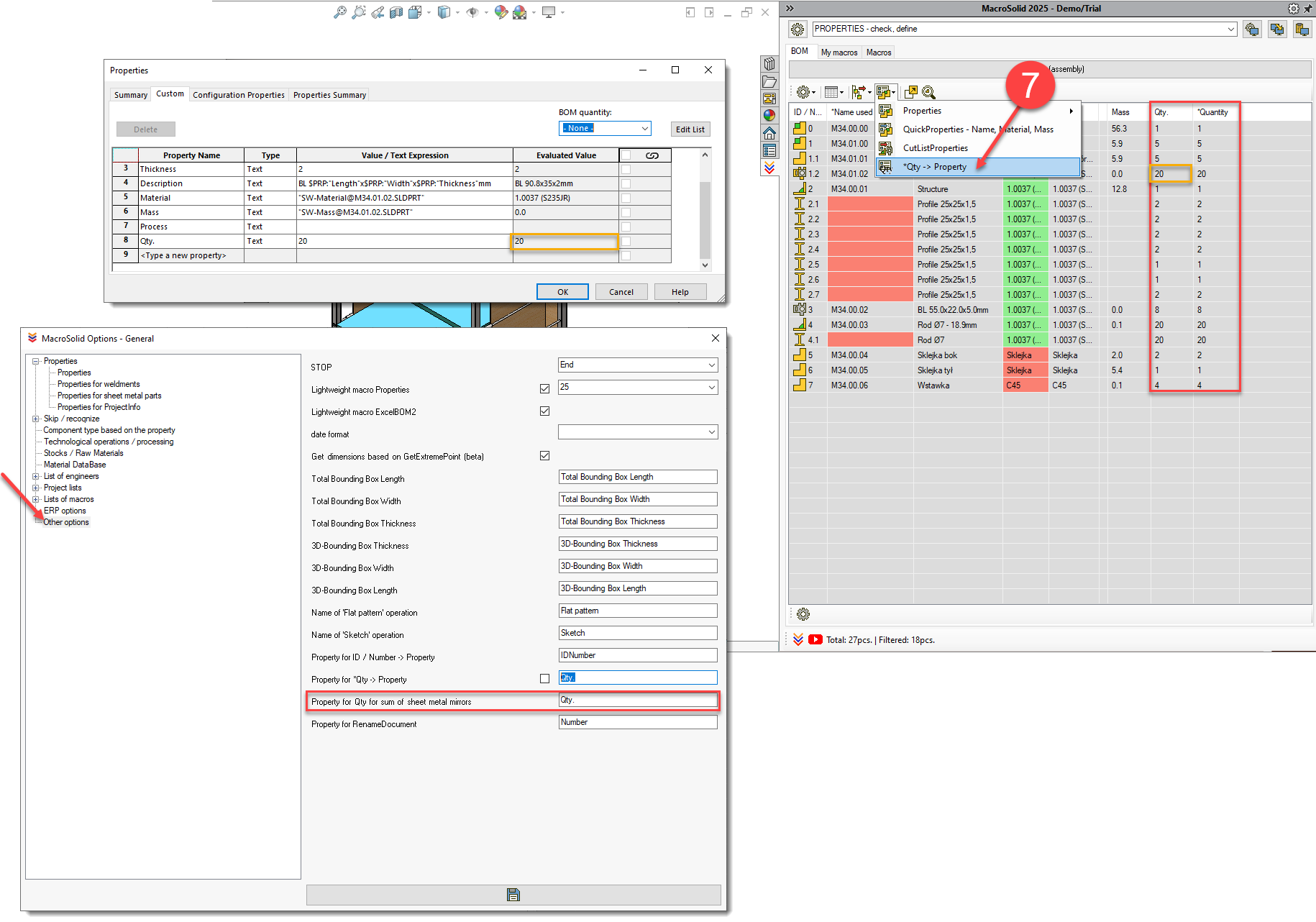
*Qty -> Property
- Run the macro that calculates the quantity (*Quantity) and saves it in the property.
- If you want to use a different property name, go to Global Settings and enter your custom name.
-
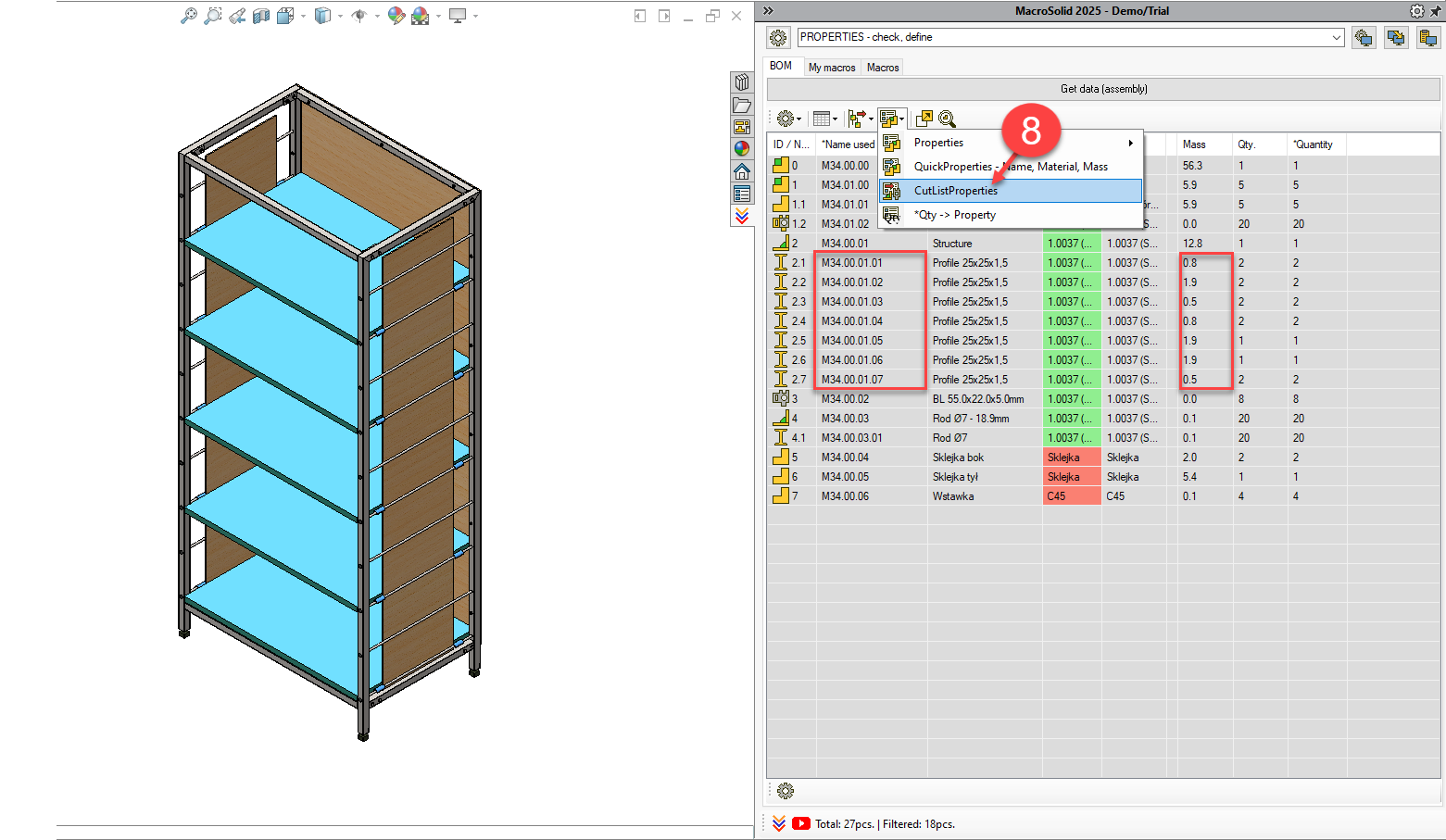
Cut list properties – CutListProperties macro
Run CutListProperties to fill in data for weldment items: Material, Mass, and Number.
📌 Info: This number will be used for generating STEP/IGES file names for profiles and DXF file names for multi-body sheet metal parts.
VIEW 4 – PROPERTIES - check, define for Toolbox and Purchased
In the previous VIEW, BOM table filtering skipped standard and purchased items. In this VIEW, the settings are reversed — we focus exclusively on components that are to be purchased or ordered.
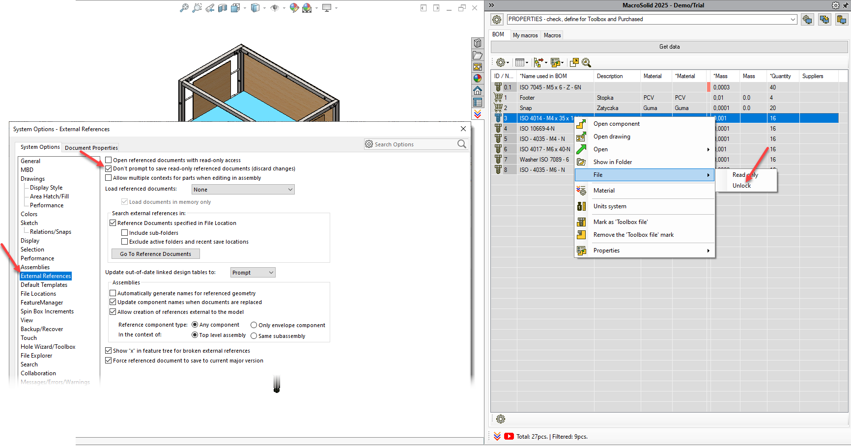
Read-only files
A gray cell in the first column indicates that the file is open as read-only.
- In a PDM system, this means the file is checked in.
- You won’t be able to save changes until the file is unlocked.
🔓 Tip: You can unlock the file status directly from the BOM table, but you’ll need to reopen the model in SOLIDWORKS® and refresh the data in MacroSolid.
⚠️ Note: If you see prompts about saving “read-only” files, enable the option:
Don’t prompt to save reference documents marked as read-only (discard changes)
(SOLIDWORKS® Settings → General)
Go to WIDOKU: PROPERTIES - check, define for Toolbox and Purchased
-
Perform steps 1–6 from the previous VIEW: PROPERTIES – check, define
Complete: Description, Material, Units, Mass as before. -
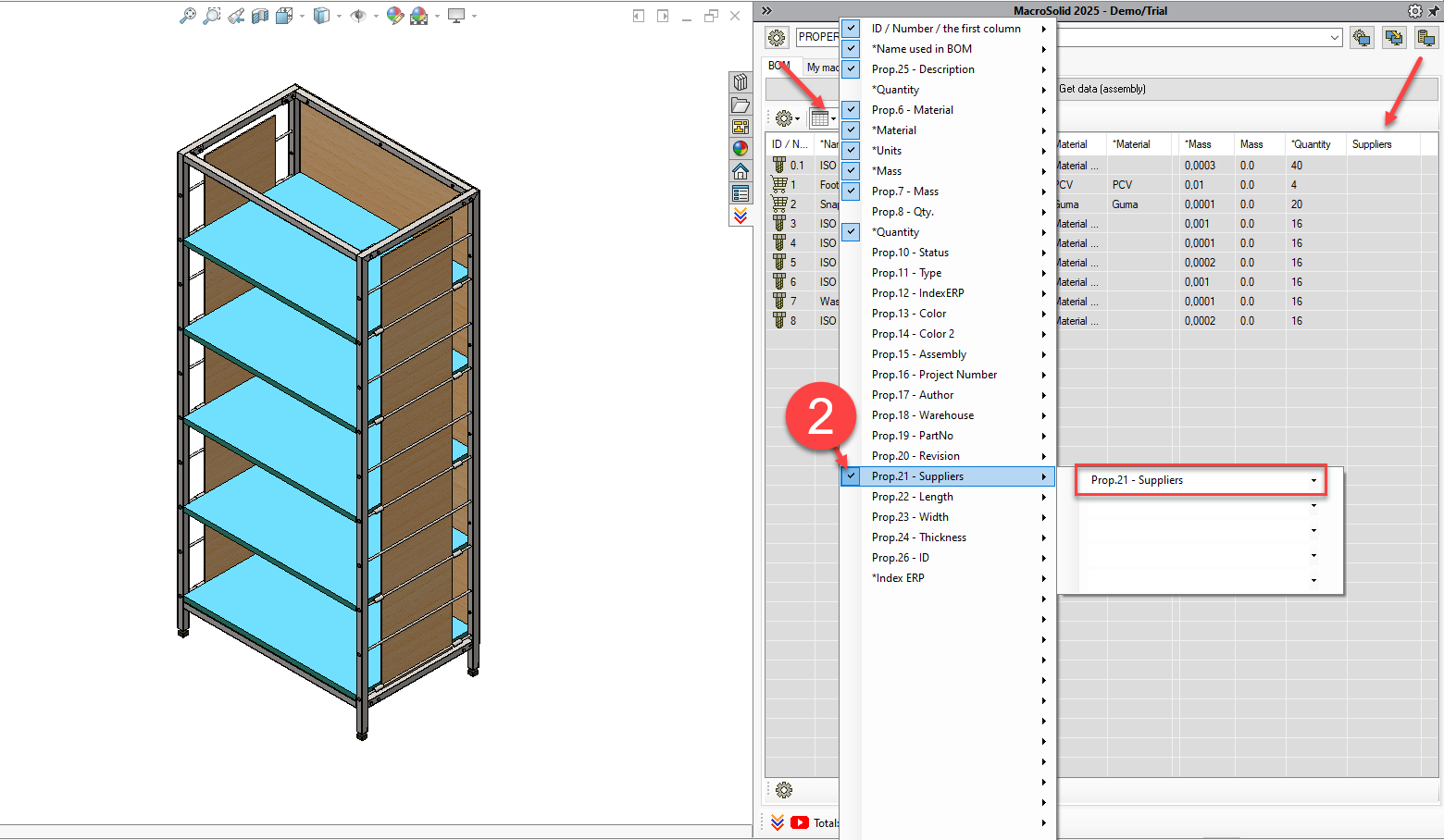
Add the Suppliers column to the BOM table
This column will be used to assign suppliers.
-
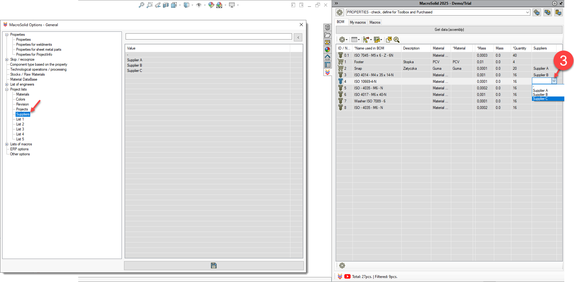
Define your supplier list in MacroSolid’s global settings
You can now double-click a cell in the Suppliers column and select a supplier from the dropdown list.
-
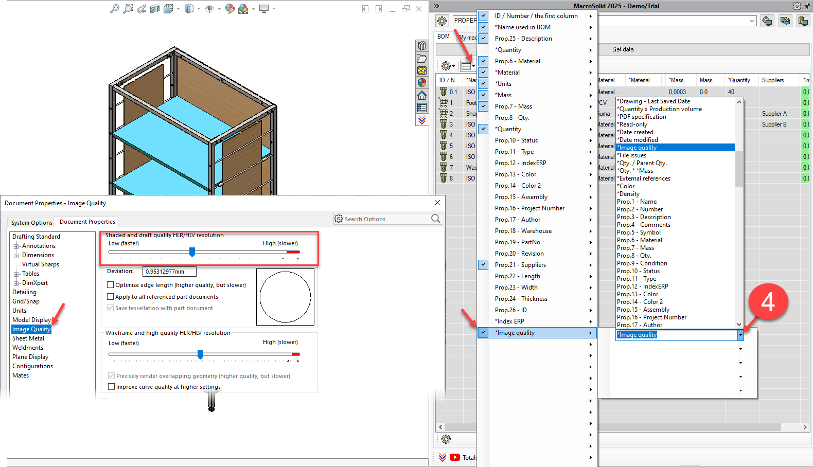
Add the *Image quality column
This helps identify models with unnecessarily high image quality settings, which can negatively impact SOLIDWORKS® performance.
-
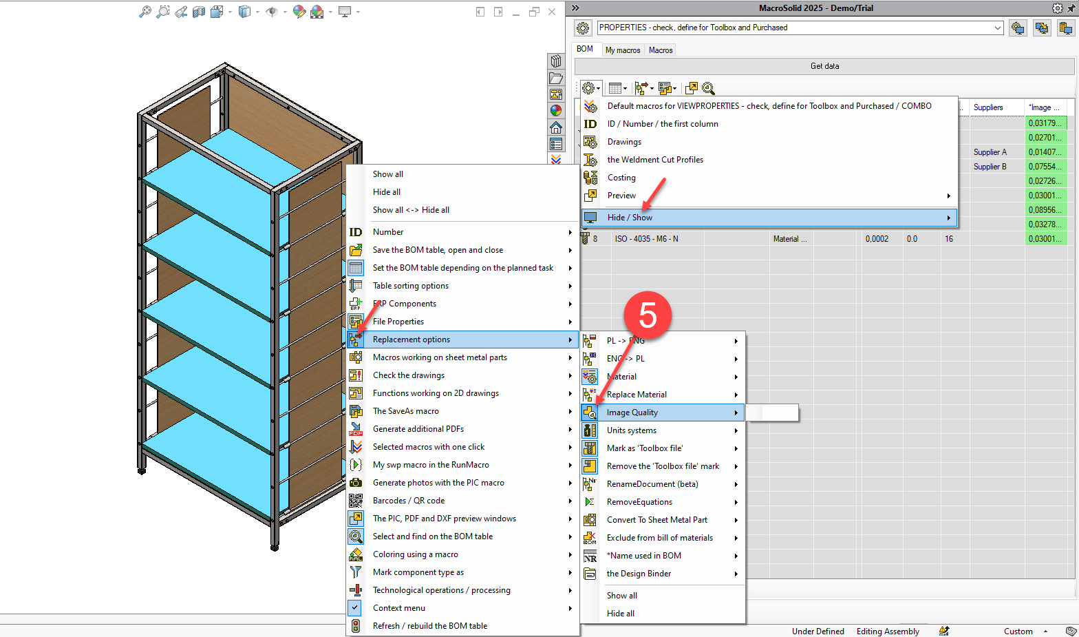
Add the MacroSolid image quality tool to this VIEW’s interface
The tool allows you to batch-change image quality settings directly from the BOM table.
-
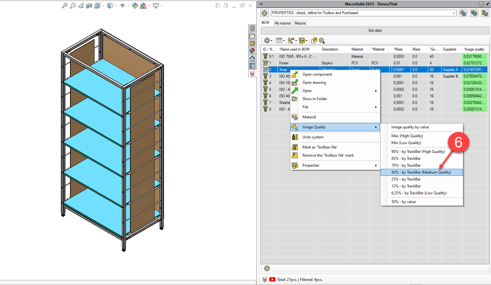
Optimize image quality for selected components
In the BOM table:
- Select all rows where the *Image quality column is highlighted in red (hold CTRL).
- Right-click and choose: 50% – by TrackBar (Medium quality).
VIEW 5 – DEFINE PROCESS
In this VIEW, you assign appropriate manufacturing operations to components, such as:
LASER, BENDING, TURNING, MILLING — in various modes:
Quick assignment (YES/NO or “x”)
Double-click the cell in the column for the desired operation to assign it:
e.g. LASER = x, BENDING = x, or TURNING = YES.
Batch assignment
You can sort the BOM table by component type, select multiple rows (using CTRL or SHIFT), and use the context menu to assign an operation to all selected components.
Operation sequence (OP.1, OP.2, …)
Each click in the next operation column assigns a sequence number:
e.g. OP.1 = LASER, OP.2 = BENDING, etc.
The properties OP.1, OP.2, OP.3 are created automatically.
Manual assignment of operations
Click a cell in the OP.1, OP.2, etc. columns and choose a value from the dropdown list.
💡 Tip: All assignments are also saved in the combined PROCESS field (e.g. PROCESS = LASER, BENDING).
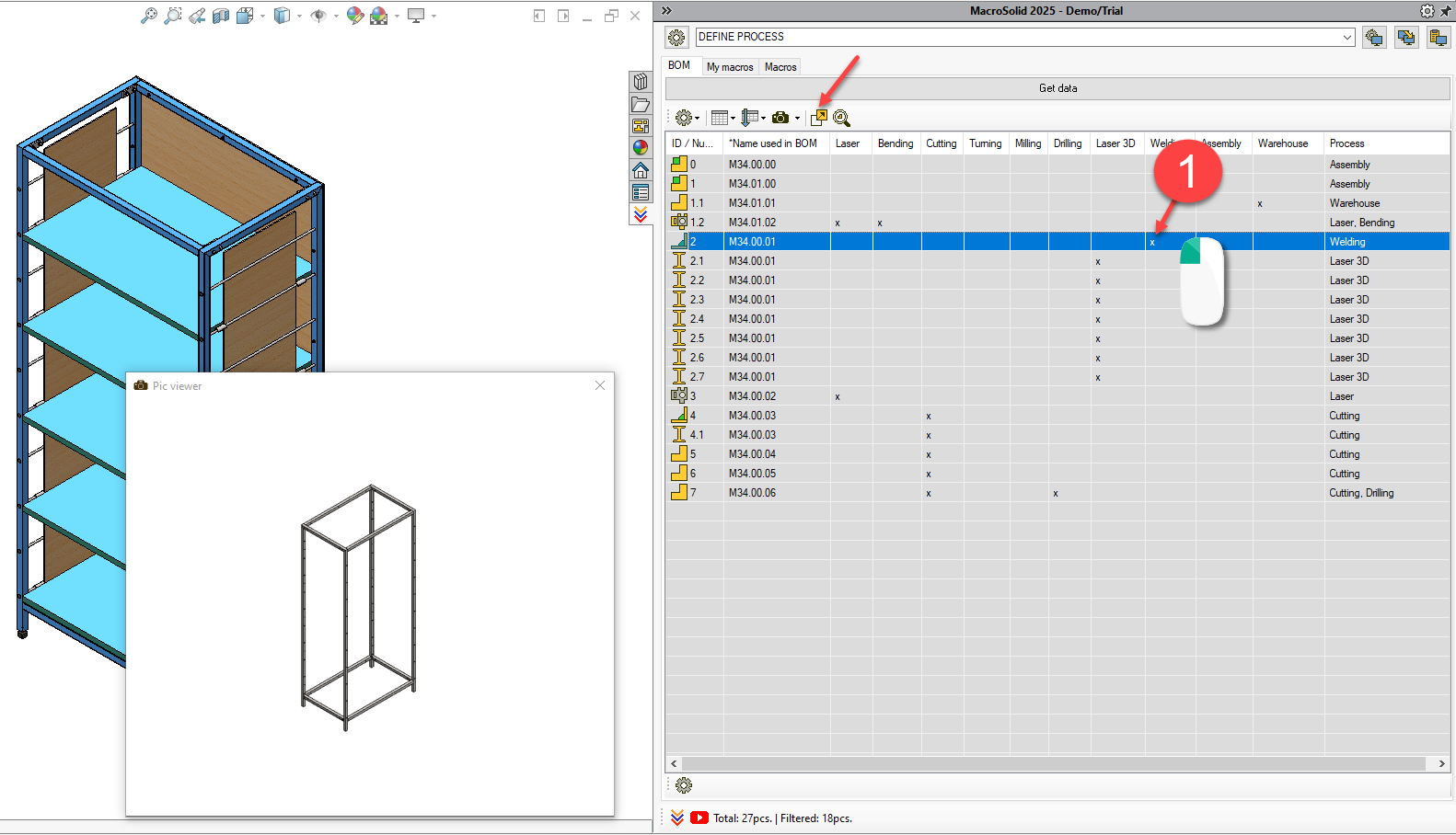
Go to VIEW: DEFINE PROCESS
-
Enable component preview
Double-click the relevant cells in the operations columns to assign processes for each row.
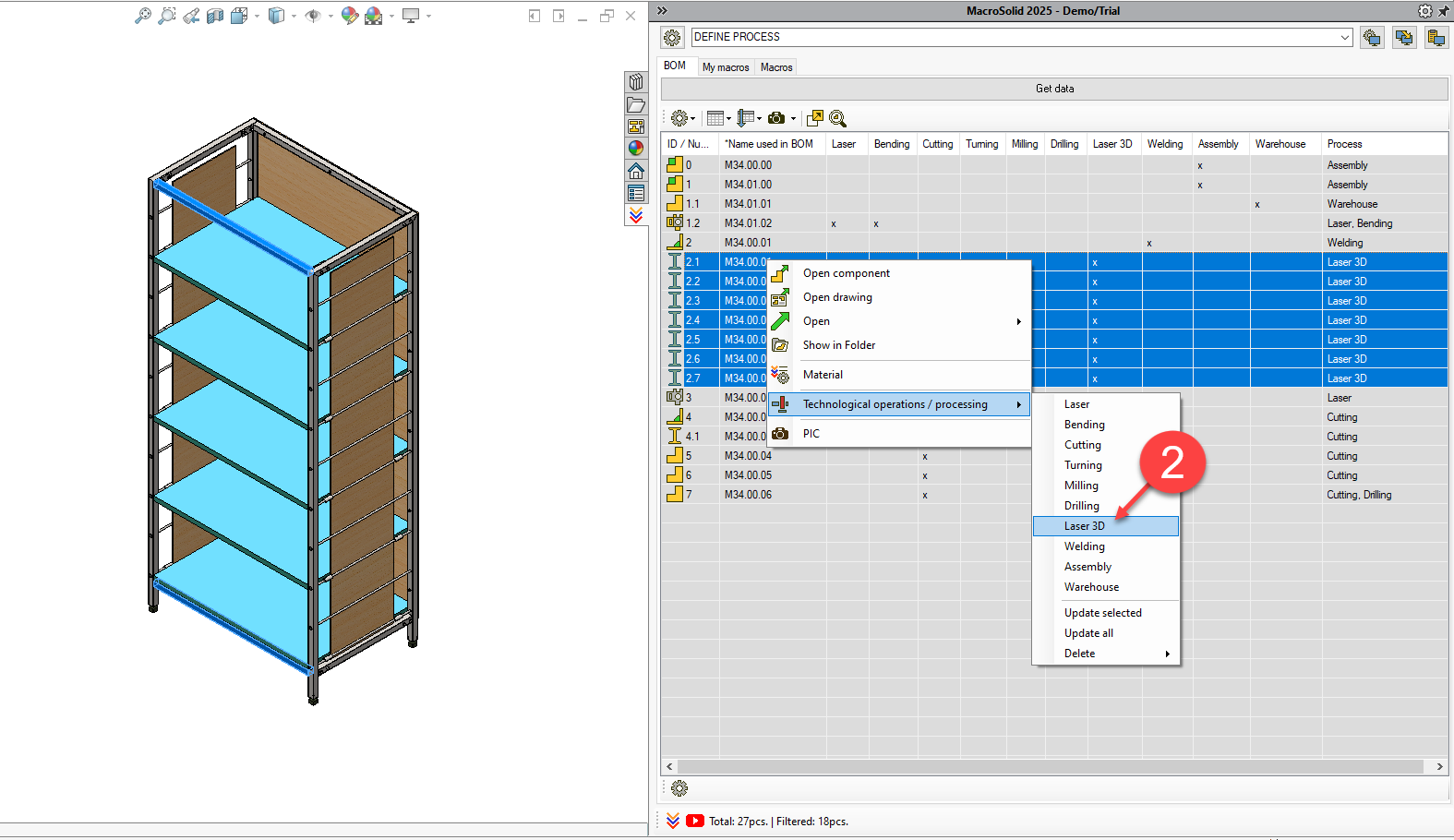
-
Assign multiple components as LASER 3D
- Select rows corresponding to profiles (with SHIFT or CTRL).
- Right-click and choose LASER 3D from the context menu.
-
Clear assigned operations
Double-click a cell in the PROCESS column, confirm the prompt — all assignments will be removed.
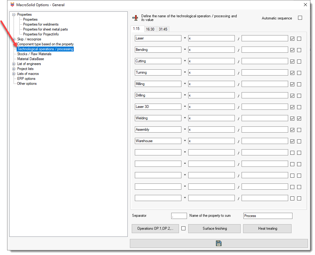
Customizing operations and order
- In MacroSolid’s main settings, you can edit:
- operation names,
- their order,
- the format in which they are saved to properties.
VIEW 6 – PAINTING, FINISHING, HEAT TREATMENT
In this VIEW, you can:
- Color the model using the RAL palette,
- Define surface finishing (e.g. ANODIZING, NICKEL PLATING),
- Specify heat treatment (e.g. HARDENING, ANNEALING).
General information
- The Colors macro uses the RAL color palette by default, but you can define your own set of colors.
- The color is applied directly in the model and saved as a custom or configuration-specific property in the file.
- Painting can be done:
- from the BOM table, or
- by clicking a model face directly in the graphics area (via the Colors macro icon in the right-click menu).
Go to VIEW: PAINTING, FINISHING, HEAT TREATMENT
-
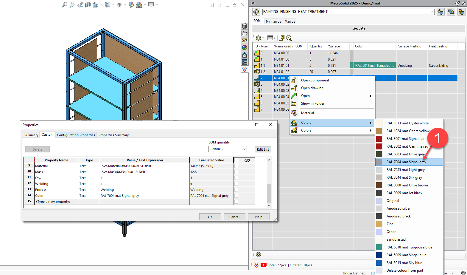
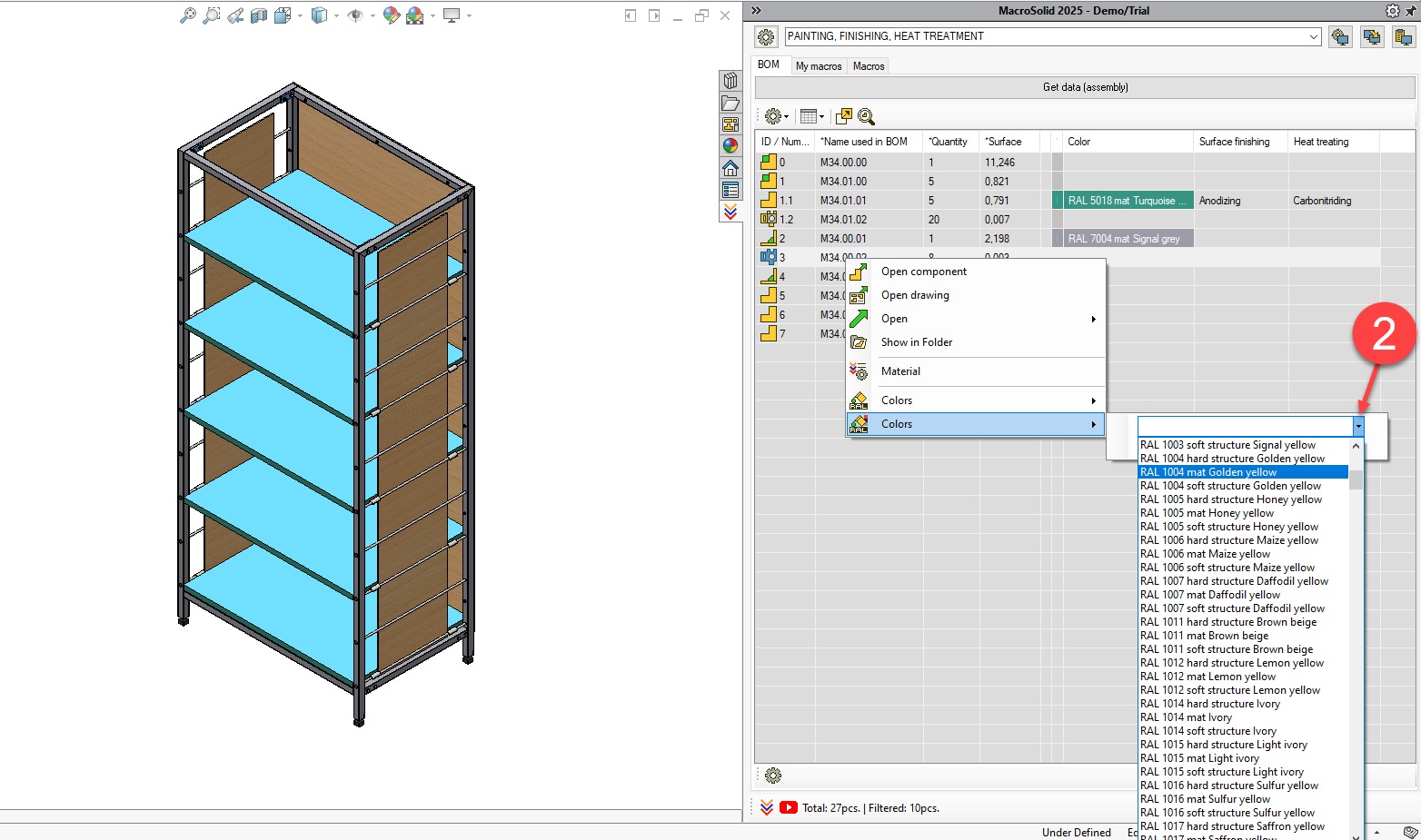
Apply an RAL color from the context menu
- Select the component rows you want to paint.
- Right-click and choose one of the commonly used colors, e.g.: RAL 7004 matte – Signal Grey
The color will be:
- applied to the model,
- saved in the Color property (for the configuration).
-
Select a color from the full RAL palette
Repeat the procedure for other components — you can use the full list of RAL colors.
-
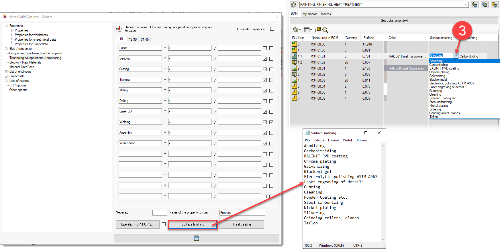
Define surface finishing
- Double-click a cell in the Finishing column.
- Select the appropriate value from the dropdown (e.g. Anodizing, Galvaning).
- The Finishing property will be assigned automatically.
⚙️ Customize the finishing list:
Go to:
MacroSolid main options → Technological operations / processing
Click Surface finishing, edit the list, save and close.
-
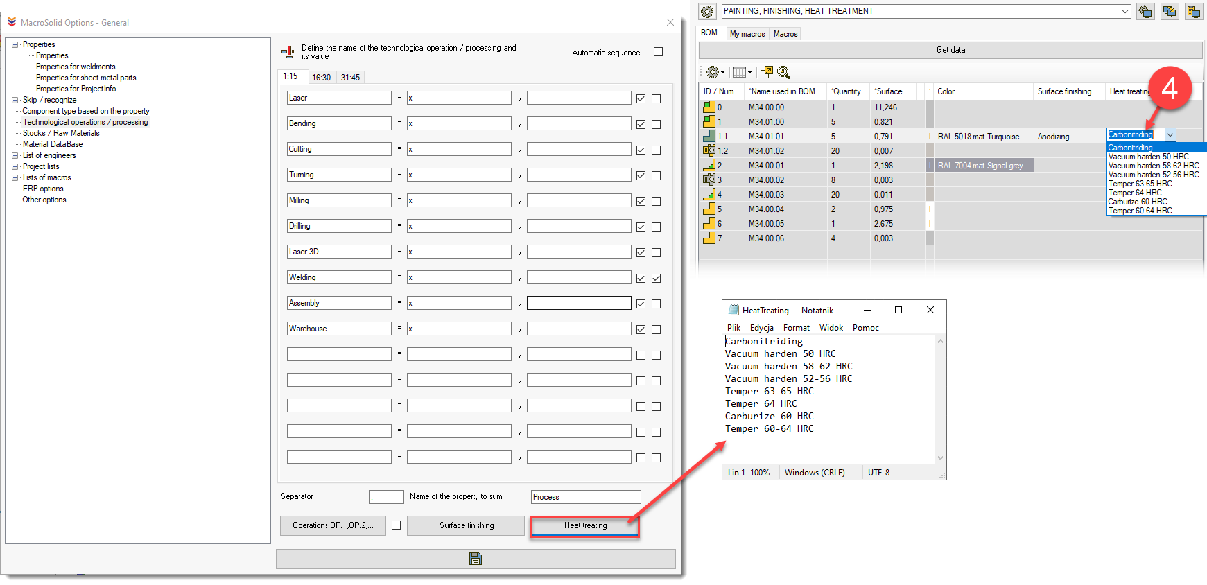
Define heat treatment
- Double-click a cell in the Heat treatment column.
- Select the appropriate value (e.g. Vacum harden, Temper) from the list.
- The Heat treatment property will be saved.
⚙️ Customize the heat treatment list:
Go to:
MacroSolid main options → Technological operations / processing
Click Heat treatment, edit the list, save and close.
VIEW 7 – Documentation – PDF, Print
This VIEW is dedicated to working with 2D documentation. It allows you to:
- generate 2D drawings for components,
- replace drawing sheet formats,
- insert barcodes,
- export to PDF, DXF, DWG,
- print completed drawings.
Go to VIEW: Documentation – PDF, Print
-
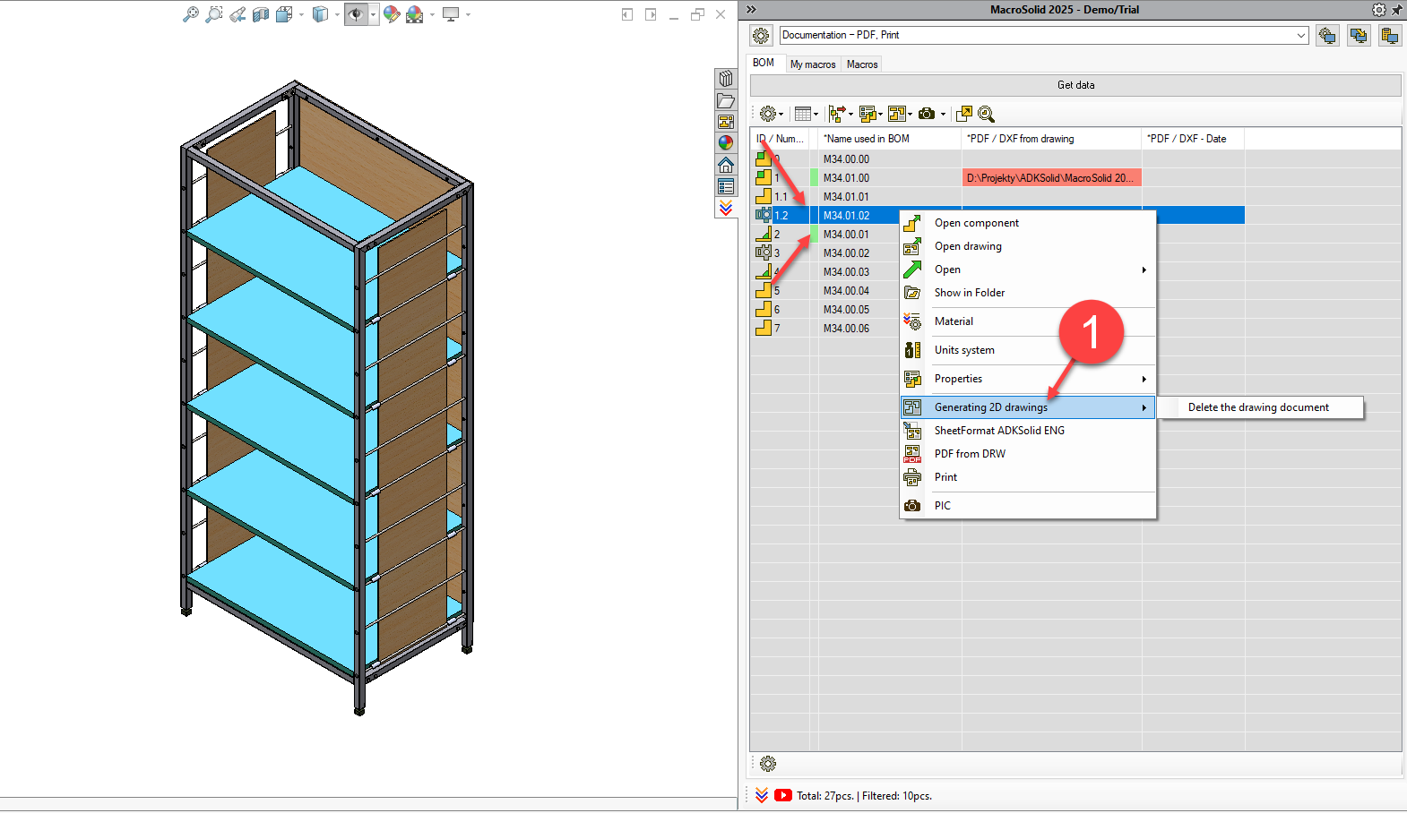
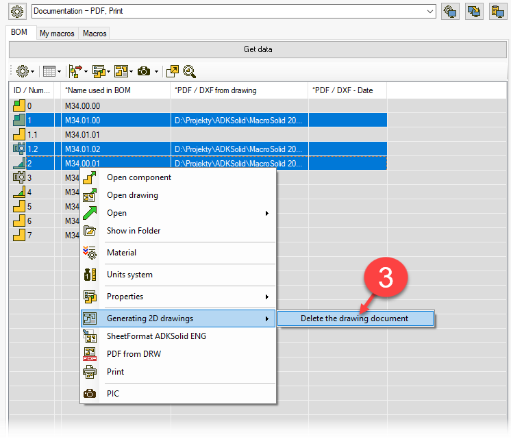
Generate new 2D drawings
- In the BOM table, select components that don’t have 2D drawings (the cell in the second column is not highlighted green).
- Hold CTRL, right-click, and choose: Generating 2D drawings.
-
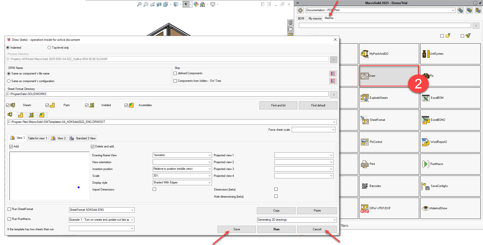
Configure the DRAW macro
- Go to the Macros tab and click the DRAW
- Choose:
- your custom drawing template (.SLDDOT),
- BOM table template,
- cut list table,
- bend table for sheet metal, etc.
- Click Save, then Cancel to close the configuration window.
-
Retest after changing settings
- Delete previously generated drawings.
- Return to step 1 and generate the drawings again using your custom templates.
-
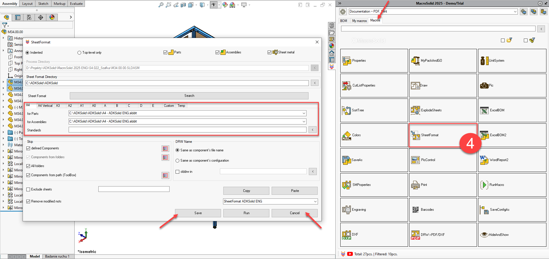
Replace outdated sheet formats (SheetFormat)
- In the SheetFormat macro settings window, assign the correct .SLDDRT files for each sheet size.
- Save the settings with Save, close the window with Cancel.
-
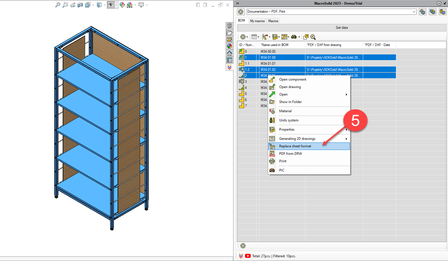
Execute sheet format replacement
- Select components in the BOM table (with CTRL).
- Right-click and choose: Replace sheet format.
-
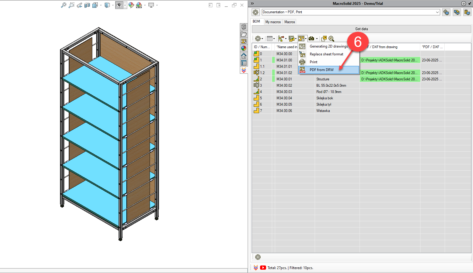
Generate PDF, DXF files
- Open the DRW → PDF/DXF macro settings window.
- Adjust export settings (e.g. target folder, file naming template, etc.).
- Click Save, close settings with Cancel.
- Go to the BOM tab and run PDF from DRW.
-
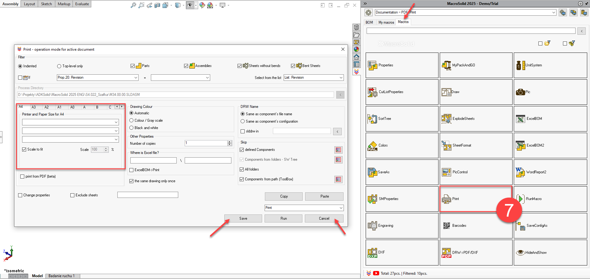
Configure print settings
- Open the Print macro settings window.
- Select the printer, paper size, and paper tray matching the drawing format.
- Save the configuration with Save, finish with Cancel.
-
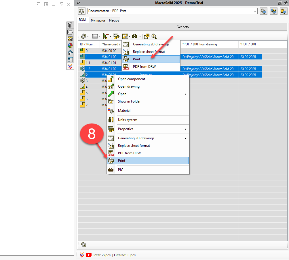
Print drawings from the BOM table
- In the BOM table, select the drawings to print (all or specific ones).
- Right-click and run the Print macro from the context menu.
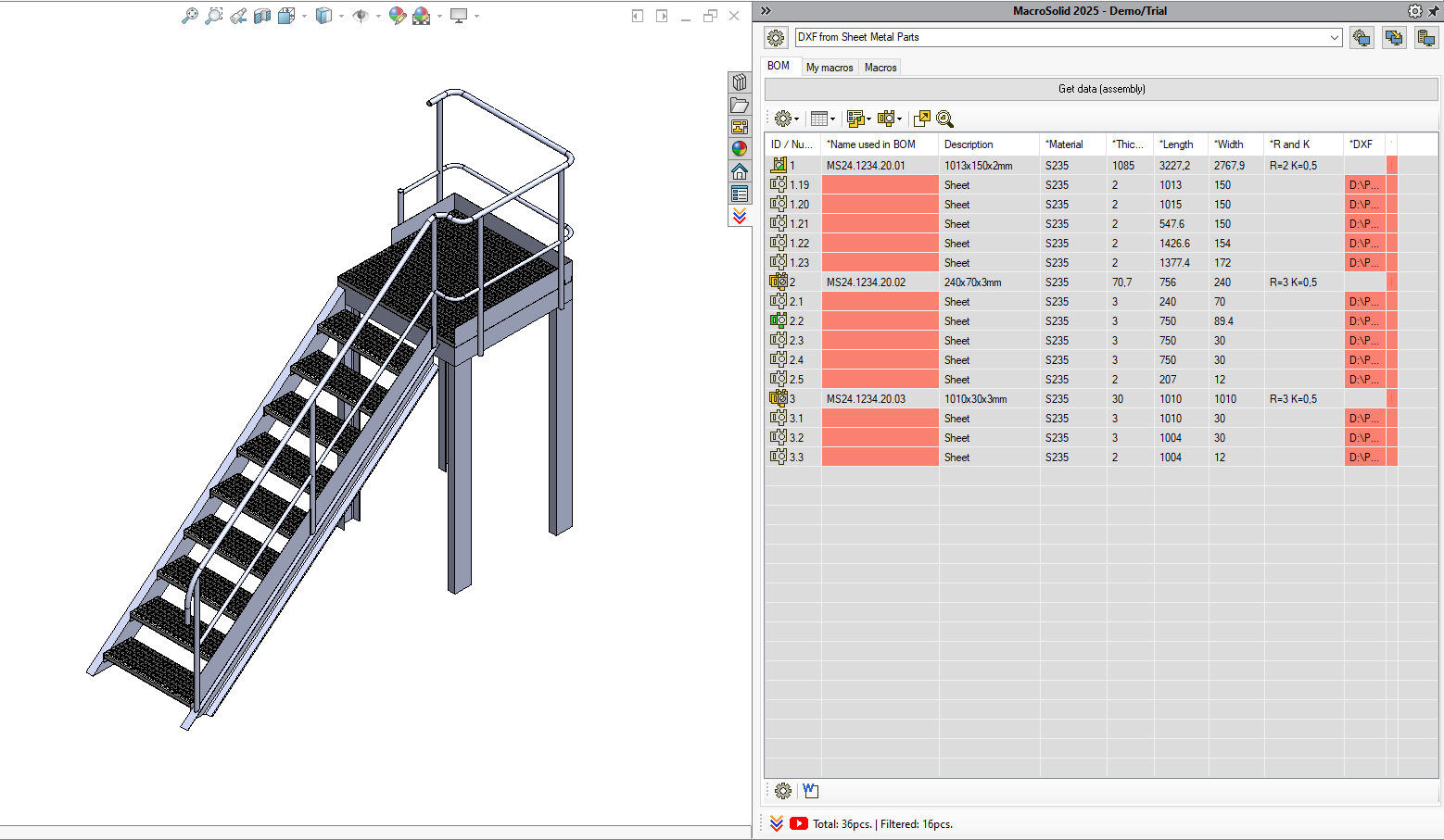
VIEW 8 - DXF from Sheet Metal Parts
This VIEW is designed specifically for working with sheet metal components.
The BOM table is filtered to show only sheet metal parts and data relevant to manufacturing.
A key feature of this VIEW is the ability to generate DXF files with options to customize:
- file names (based on properties),
- save location,
- layer mapping,
- modification of holes created with the Hole Wizard so that the DXF files don’t require manual editing.
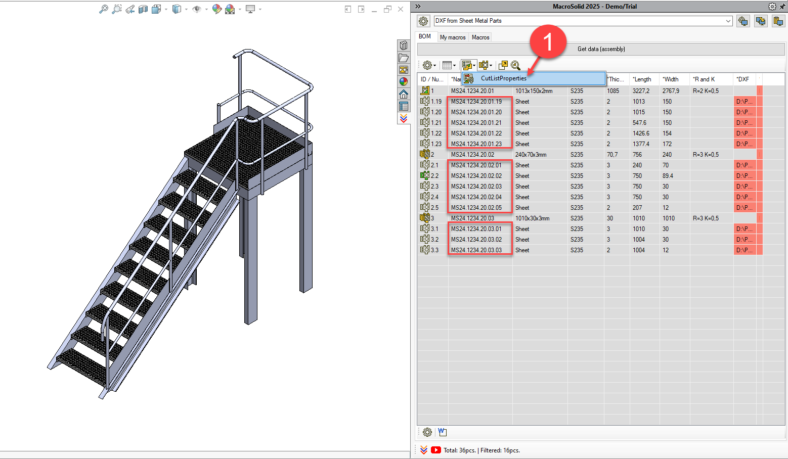
⚠️ Warning: BOM Name
If the *Name used in BOM column contains red-highlighted cells, this means:
- the CutListProperties macro has not been run,
- and the Number property needed to build a unique DXF file name is missing.
🔧 For multi-body models (e.g. weldments), the Number property is essential for distinguishing between sheet metal cut list items / DXF files.
📌 For single-body parts (one file = one sheet metal part), identification is simpler and does not require additional numbers.
Go to VIEW: DXF from Sheet Metal Parts
-
Run the CutListProperties macro
Właściwość Numer zostanie utworzona automatycznie (nazwa pliku + ID elementu ciętego).
If you see red-highlighted cells in the *Name used in BOM column, run CutListProperties for the model.
The Number property will be generated automatically (file name + cut list item ID).
-
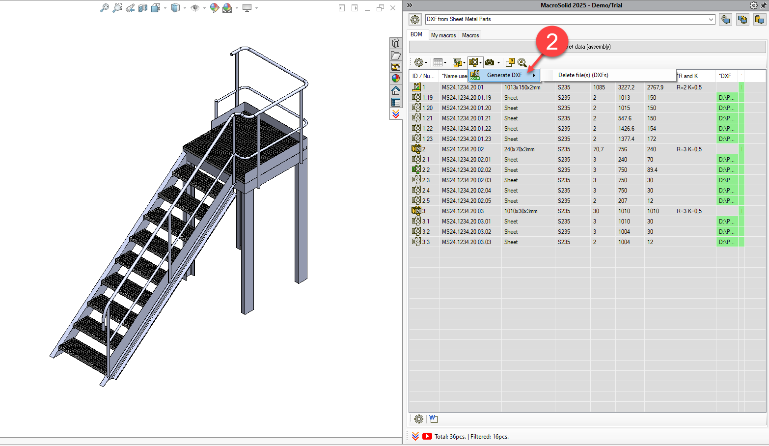
Generate DXF files
- In the BOM table:
- Select all or specific rows (with CTRL or SHIFT)
- Right-click and choose Generate DXF from the context menu
✅ Note: The DXF macro can only run if no cells in the *Name used in BOM column are highlighted in red.
-
Generate a sheet metal summary report in MS Word®
Run the macro to create a Word document summarizing the sheet metal parts.
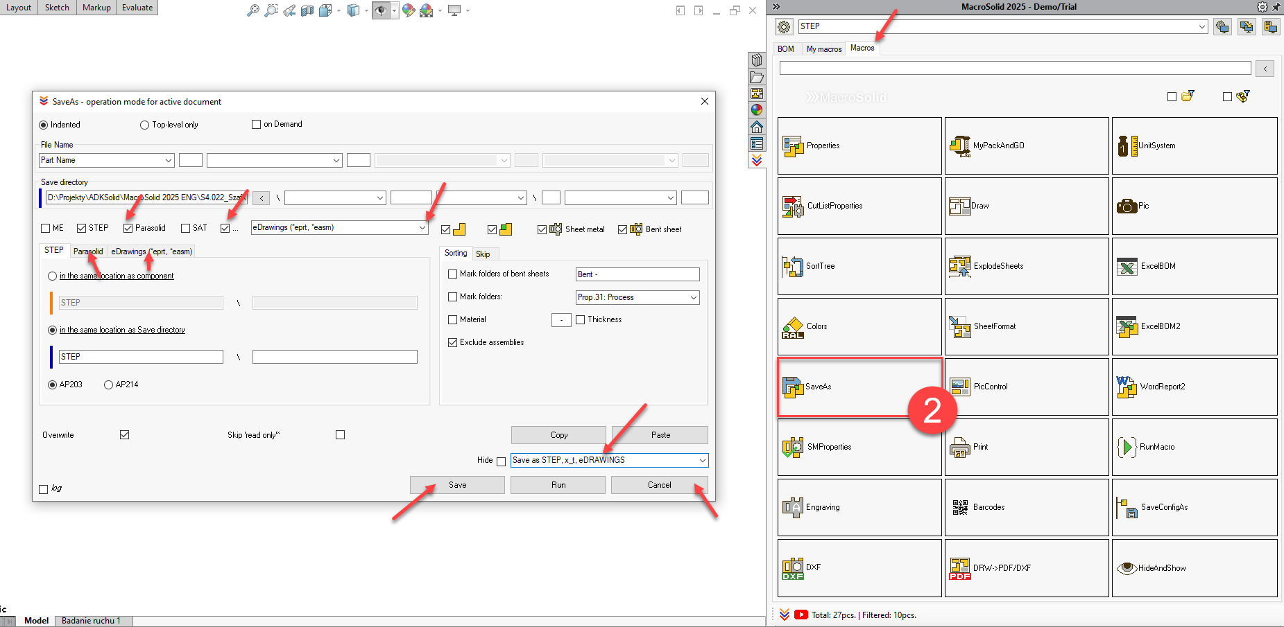
VIEW 9 - STEP
The SaveAs macro allows quick export of files to various formats — with a single click you can save:
- STEP (.step, .stp)
- Parasolid (.x_t)
- SAT (.sat)
- and one additional selected format, e.g. 3D PDF, eDrawings (.eprt, .easm)
Files can be exported:
- for the entire project,
- for filtered elements,
- or only for selected components in the BOM table.
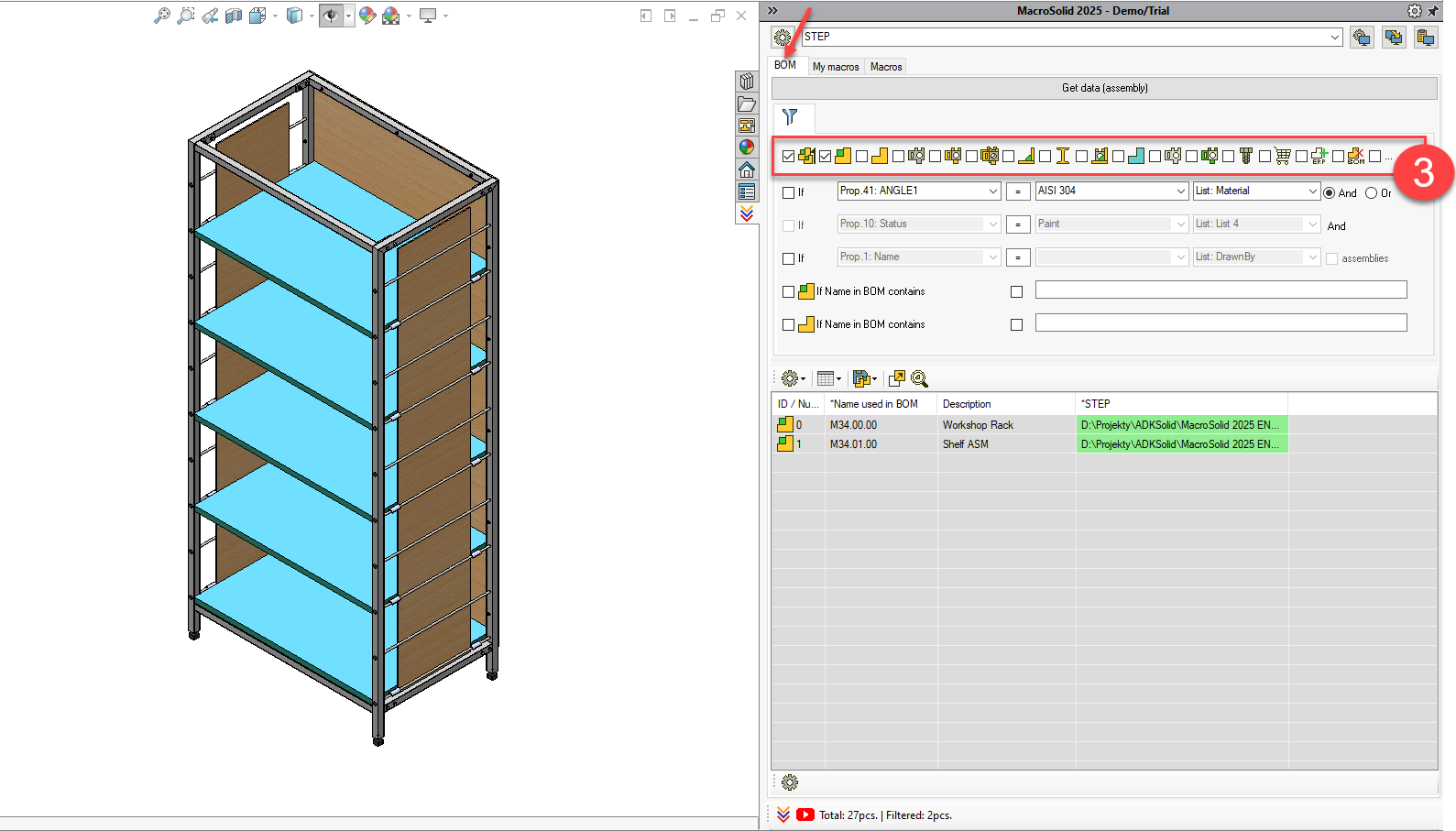
Go to VIEW: STEP
-
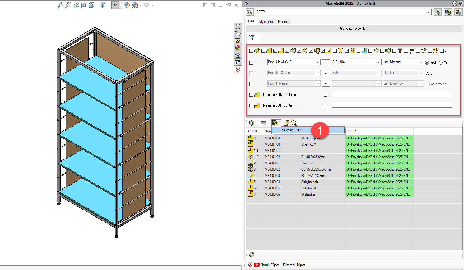
Export STEP files (excluding purchased parts)
- Set the filter to hide purchased components.
- Select the components (or leave all visible ones selected).
- Run the SaveAs macro from the context menu.
-
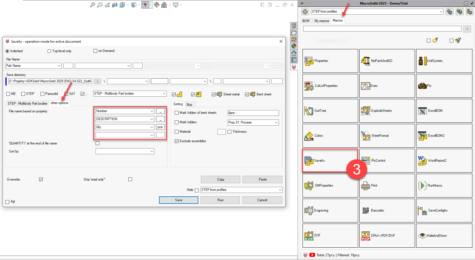
Configure the SaveAs macro – multi-format export
- Go to the Macros tab and click the SaveAs
- In the configuration window:
- Select the Parasolid (.x_t) option,
- From the dropdown, choose an additional format, e.g. eDrawings (.eprt or .easm),
- Define separate save folders for each format,
- Rename the setting (e.g. STEP, x_t, eDraw), click Save, then Cancel to close the window.
-
Prepare to export the main assembly and subassemblies
- Return to the BOM tab.
- Adjust the filter so that the main assembly and its subassemblies are visible.
-
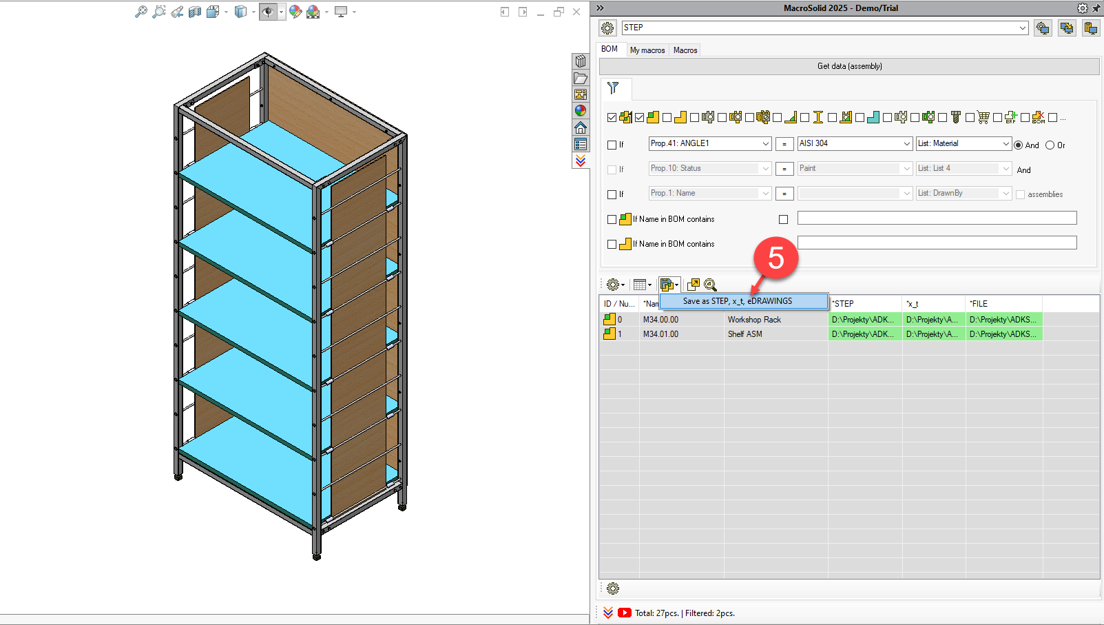
Add columns for output file information
- Add two new columns to the BOM table:
- *x_t - path to the exported Parasolid file,
- *FILE - path to the file in the additional format (e.g. eDrawings).

-
Run the export
Launch the SaveAs macro from the Macros tab or the BOM table’s context menu.
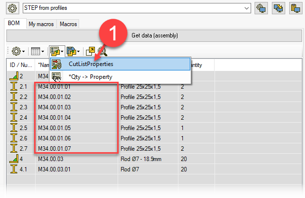
VIEW 10 - STEP from profiles
For single-body profiles in multi-body models, a unique name for each component is essential for correct STEP or IGES export.
Key information:
- The Number property (file name + cut list item ID), generated by the CutListProperties macro, is the basis for creating unique file names.
- Without this property, error-free export is impossible — this issue is indicated by red-highlighted cells in the *Name used in BOM column.
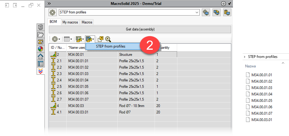
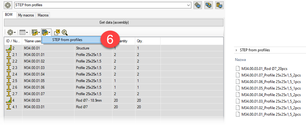
Go to VIEW: STEP from profiles

-
Check and prepare the data
If the *Name used in BOM column contains red-highlighted cells, run CutListProperties — this will assign a unique Number property.
-
Export STEP files from the BOM table
- Once you’ve confirmed there are no red cells in *Name used in BOM:
- Select profiles in the BOM table (all or chosen ones).
- Right-click and select STEP from PROFILES from the context menu.
-
Configure STEP / IGES file naming
- Go to the Macros tab and click SaveAs.
- In the settings editor, adjust the file name template to include:
- profile type (e.g. L, C, RHS),
- Save the modified setting with Save, close the window with Cancel.
-
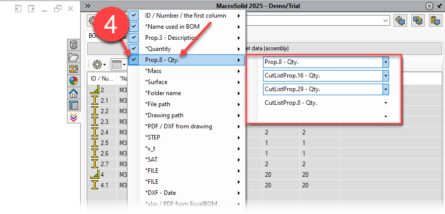
Add a column with quantity information
In the BOM table, add a column that displays the Qty. property value.
-
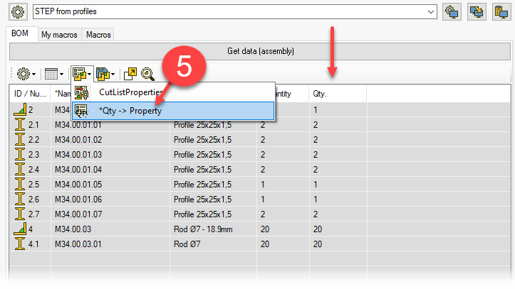
Populate the Qty. property
Run the special macro *Qty. → Property — this copies the value from the *Quantity column to the Qty. property.
-
Final export with the planned file name
- Run the SaveAs macro again to generate files:
- STEP or IGES,
- with a name that includes profile description and quantity.
✅ Example file name: FileName_L-50x5_S235_4pcs.STEP
VIEW 11 - BOM
MacroSolid allows you to automatically generate a Bill of Materials (BOM) into an MS Excel® file based on predefined templates.
The file will be saved in the main assembly folder.
Go to VIEW: BOM
-
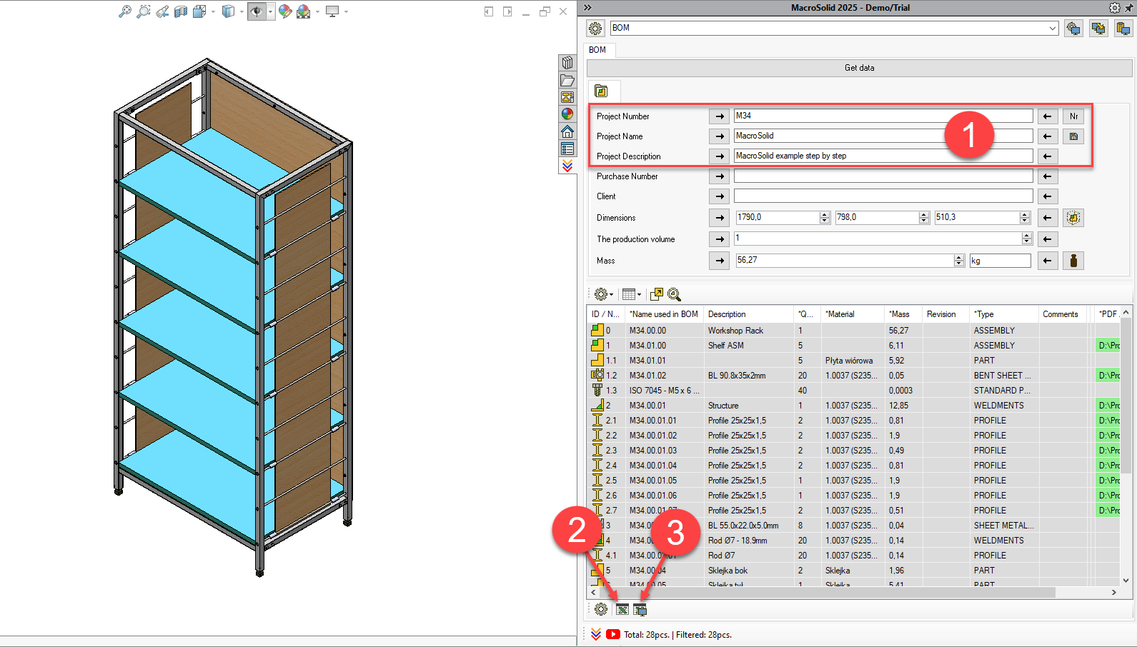
Fill in the project data
- Open the ProjectInfo panel.
- Enter the project identification data (e.g. project number, name, client, date).
-
Generate the basic BOM
- Run the macro that generates the BOM to Excel®.
- The BOM will be created according to the default .xlsx template and saved in the project’s main folder.
-
Generate a BOM with separate sheets
- You can generate an Excel® file with separate tabs such as:
- BILL OF MATERIALS (full list),
- SHEET METAL PARTS,
- PROFILES,
- STANDARD PARTS and PURCHASED ITEMS.
- Use the appropriate setting in the macro to activate this split.
- You can generate an Excel® file with separate tabs such as:
Customizing the template
You can customize the Excel template to fit your needs:
- column layout,
- formatting,
- logo,
- additional information.
📘 Detailed configuration guide available at: https://adksolid.com/en/macros-solidworks/makro-solidworks-excelbom2
Copyright © ADKSolid. All rights reserved


