


MacroSolid - Draw
The DRAW macro is our answer to the frequently asked question: "Is it possible to develop a macro that will create technical documentation for us?". Our answer is always the same: "Macro will not replace a human being, but yes, in a certain scope of work related to the development of technical drawings, an automatic machine can replace the constructor."
We took up the challenge - we are working on the DRAW macro to get the most out of SOLIDWORKS as much as possible in terms of automatic generation of 2D drawings.
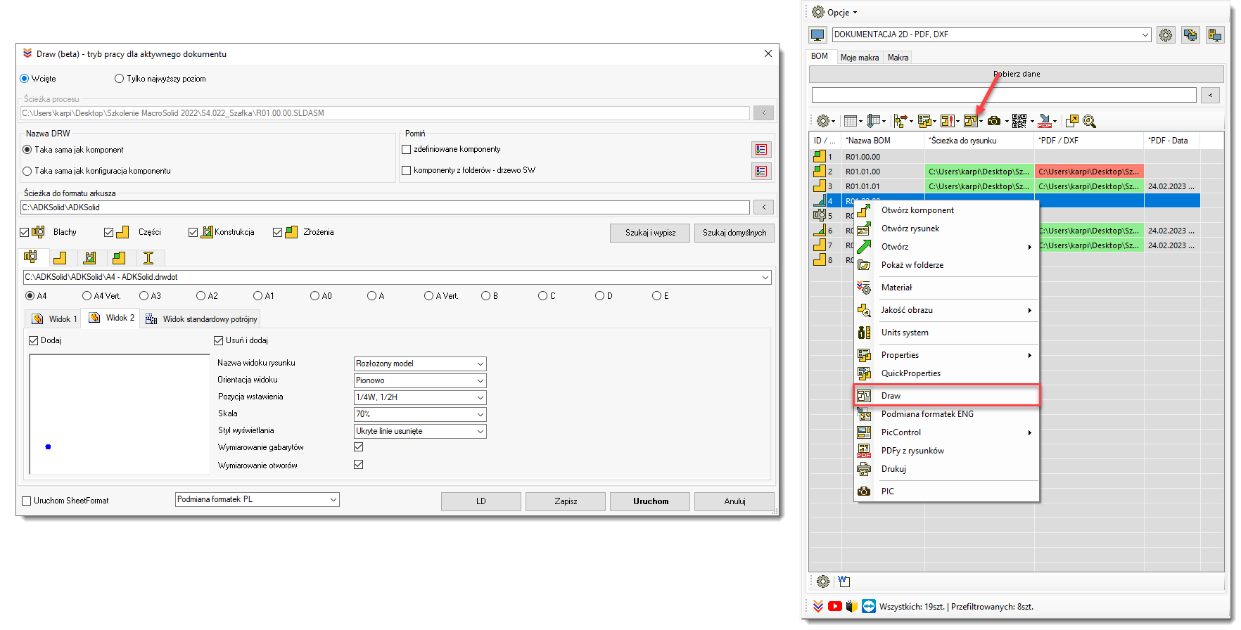
Appropriate configuration of the MacroSolid VIEW will allow you to see if and where drawings exist and where they do not. The DRAW macro can be run for all or only for selected rows / components, which will "create" 2D drawings, i.e. create SLDDRW documents starting from the selected DRWDOT template and then save with the appropriate name and in the appropriate location.
In the current version of the software, it is possible to independently plan drawings for parts, sheet metal, weldments and assemblies. Planning is understood here as configuring the behavior of this automaton. For example, you can add two views for the *Front and *Isometric parts, and for the *Isometric and "Exploded model" parts, indicating the position of the center of the view or selecting one of the selected positions in relation to the height and width of the sheet, e.g. ¼ width and ½ height (1/4W, 1/2H). For assembly drawings and welded structures, you will also add two views, the first also with references and a table based on the .sldbomtbt bill of materials template and the .sldwldtbt cut list template.
In addition to the insertion position, the orientation and scale in which the view is displayed are also important. The DRAW macro can add a view as suggested by SOLIDWORKS®, but also rotate it to display vertically or horizontally. Next, the scale of the view is considered, which can be the same as the scale of the sheet, selected from the palette of standard ones or selected by the DRAW macro on the basis of the percentage of the area reached, e.g. if the view is inserted vertically in scale = 50%, the macro will add the view, rotate vertically and then selected the scale from the smallest to the one that will be or will reach 50% of the sheet height.
Preparing your own templates seems to be crucial. The template should have document properties already defined. Pay particular attention to the "Detailing" tab in the "Auto insert on view creation" section. These are the options that cause elements such as center marks, symbols, center lines, references to be automatically generated when a view is added. Units, default fonts, arrowheads, and many other aspects of how a drawing looks depends on the document property settings that come with the template. The template also stores layers to which drawing elements can be assigned automatically. When dimensioning, inserting a table, we do not think about it - these elements of the drawing assign themselves to the appropriate layers, but this should be specified in the document properties options.
When it comes to tables, you should remember about anchors - points to which tables will be automatically attached. Of course, it is necessary to prepare individual table templates as well as the sheet title table itself. Inserting a view should autocomplete the contents of the title table, and inserting a list of materials should take two or three clicks.
We are currently working on the function of automatic dimensioning of holes and dimensions. In the case of "simple" details and sheets, the developed algorithm is already working, but with more complex shapes it may still have problems. This is why …. The race against time continues. We continue programming so that in the near future you can only focus on making your documentation more detailed.
Copyright © ADKSolid. All rights reserved.


