


What's New in MacroSolid
![]() Until now, there was no need for it, but it has finally arisen — we've added an option to include the first ID / Number column when generating the CSV file.
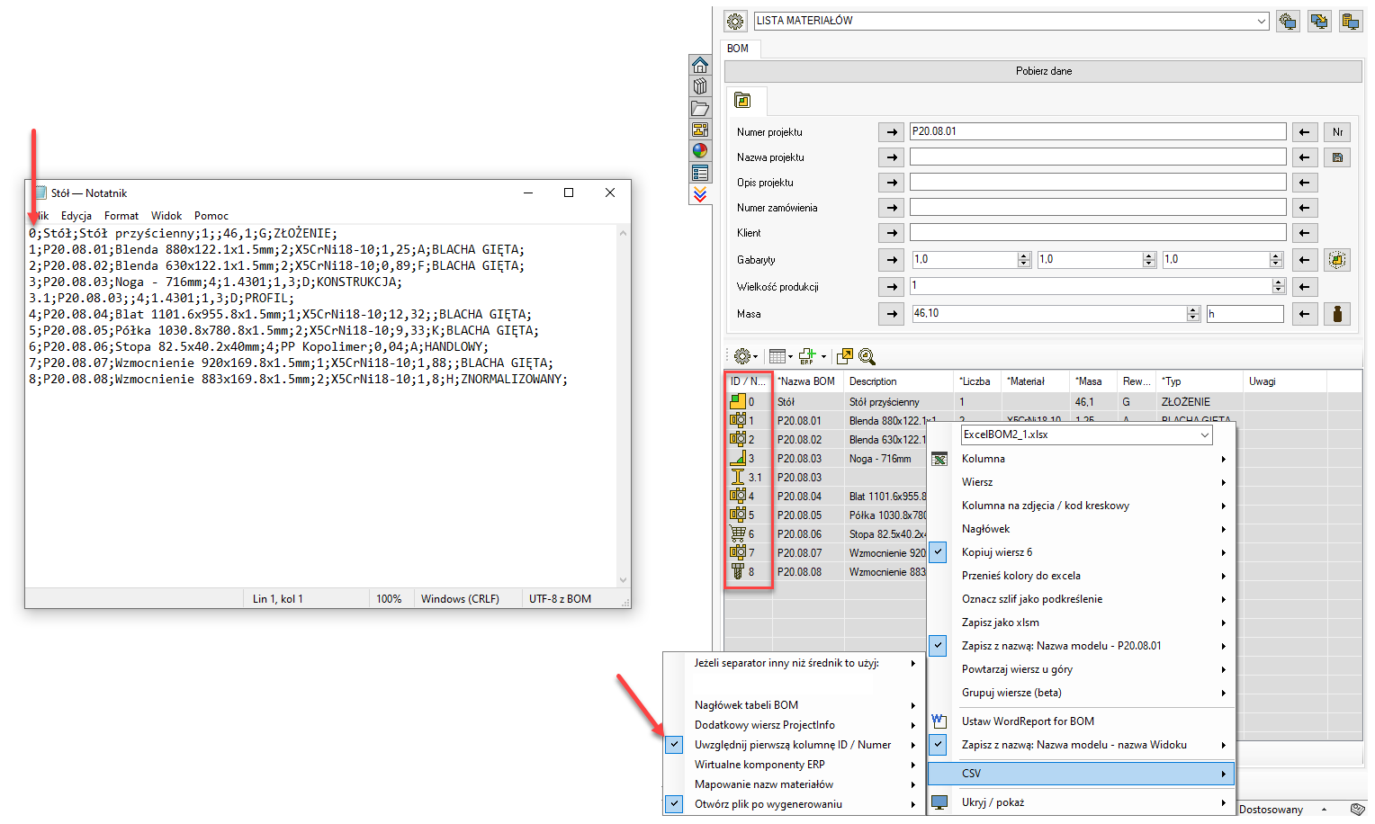
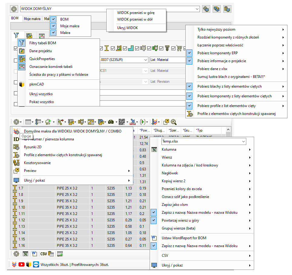
Until now, there was no need for it, but it has finally arisen — we've added an option to include the first ID / Number column when generating the CSV file.
![]() In the mode for defining subsequent operations (OP.1, OP.2, OP.3, etc.), it is possible to assign a separate list to each operation. If you want to use this approach, prepare individual files: ListaOperacji1.txt for OP.1, ListaOperacji2.txt for OP.2, and so on.
In the mode for defining subsequent operations (OP.1, OP.2, OP.3, etc.), it is possible to assign a separate list to each operation. If you want to use this approach, prepare individual files: ListaOperacji1.txt for OP.1, ListaOperacji2.txt for OP.2, and so on.
If the file ListaOperacji1.txt is empty, the software will interpret this as a signal to display all operations from the main list, ListaOperacji.txt, in that column.

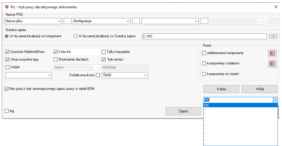
![]() We’ve added two new options to the PIC macro that allow you to automatically skip generating previews for components that already have saved images. In large projects, manually selecting components and running the PIC macro from the context menu to generate PNG files can be tedious. Thanks to the new options, you no longer need to worry about which components have previews and which don’t — just click the PIC icon above the BOM table, and the macro will take care of the rest.
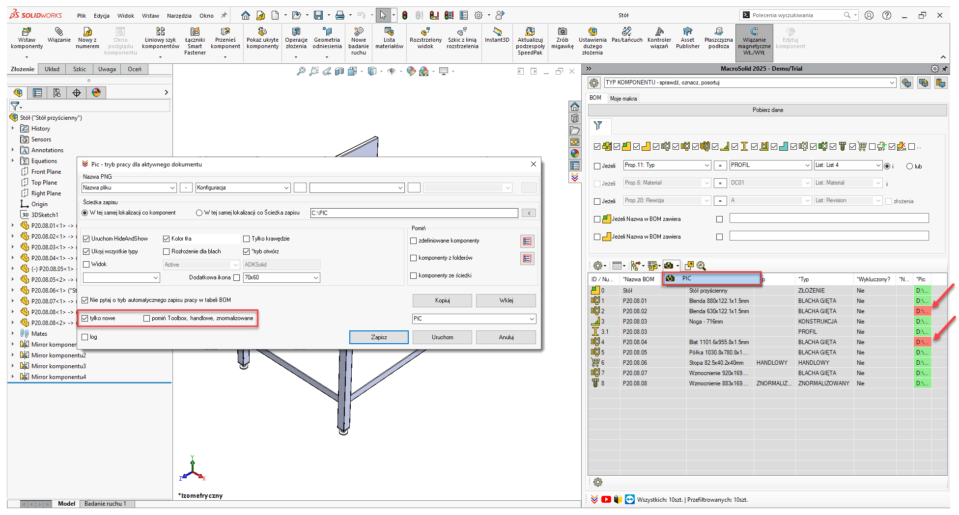
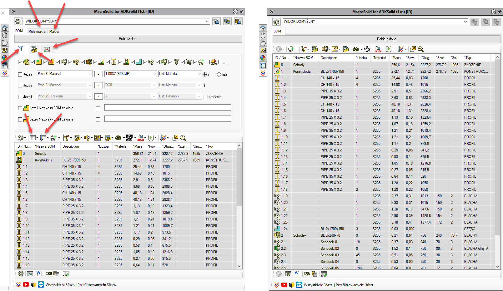
We’ve added two new options to the PIC macro that allow you to automatically skip generating previews for components that already have saved images. In large projects, manually selecting components and running the PIC macro from the context menu to generate PNG files can be tedious. Thanks to the new options, you no longer need to worry about which components have previews and which don’t — just click the PIC icon above the BOM table, and the macro will take care of the rest.
![]() We’ve improved the printing of multi-sheet drawings — if all sheets in the document are the same size, duplex printing will now work correctly.
We’ve improved the printing of multi-sheet drawings — if all sheets in the document are the same size, duplex printing will now work correctly.
![]() Until now, BOMs generated from a VIEW could be saved in XLSX and DOCX formats with a filename matching the model name or the model name extended by a separator and the VIEW name. Now, you can also include information defined in the ProjectInfo panel in the file name.
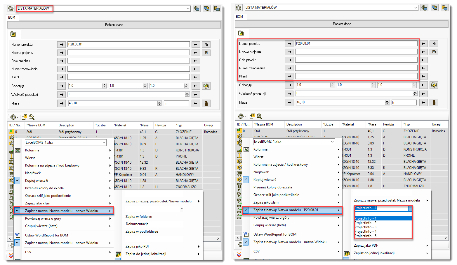
Until now, BOMs generated from a VIEW could be saved in XLSX and DOCX formats with a filename matching the model name or the model name extended by a separator and the VIEW name. Now, you can also include information defined in the ProjectInfo panel in the file name.
![]() We’ve added a new control above the BOM table to specify the save path for the “MyPackAndGo for...” function. If the path is set, all files will be saved to that location. This is a global setting — it applies to the entire add-in. This means that regardless of the path specified in individual views within “MyPackAndGo for...”, the files will still be saved to the location defined in the control above the BOM table.
We’ve added a new control above the BOM table to specify the save path for the “MyPackAndGo for...” function. If the path is set, all files will be saved to that location. This is a global setting — it applies to the entire add-in. This means that regardless of the path specified in individual views within “MyPackAndGo for...”, the files will still be saved to the location defined in the control above the BOM table.
![]() If stock levels are retrieved from the ERP system via CSV, there may be a need to add something to the SOLIDWORKS® project that doesn't yet exist in the ERP. In such cases, a temporary Virtual ERP Component needs to be created. We've got you covered.
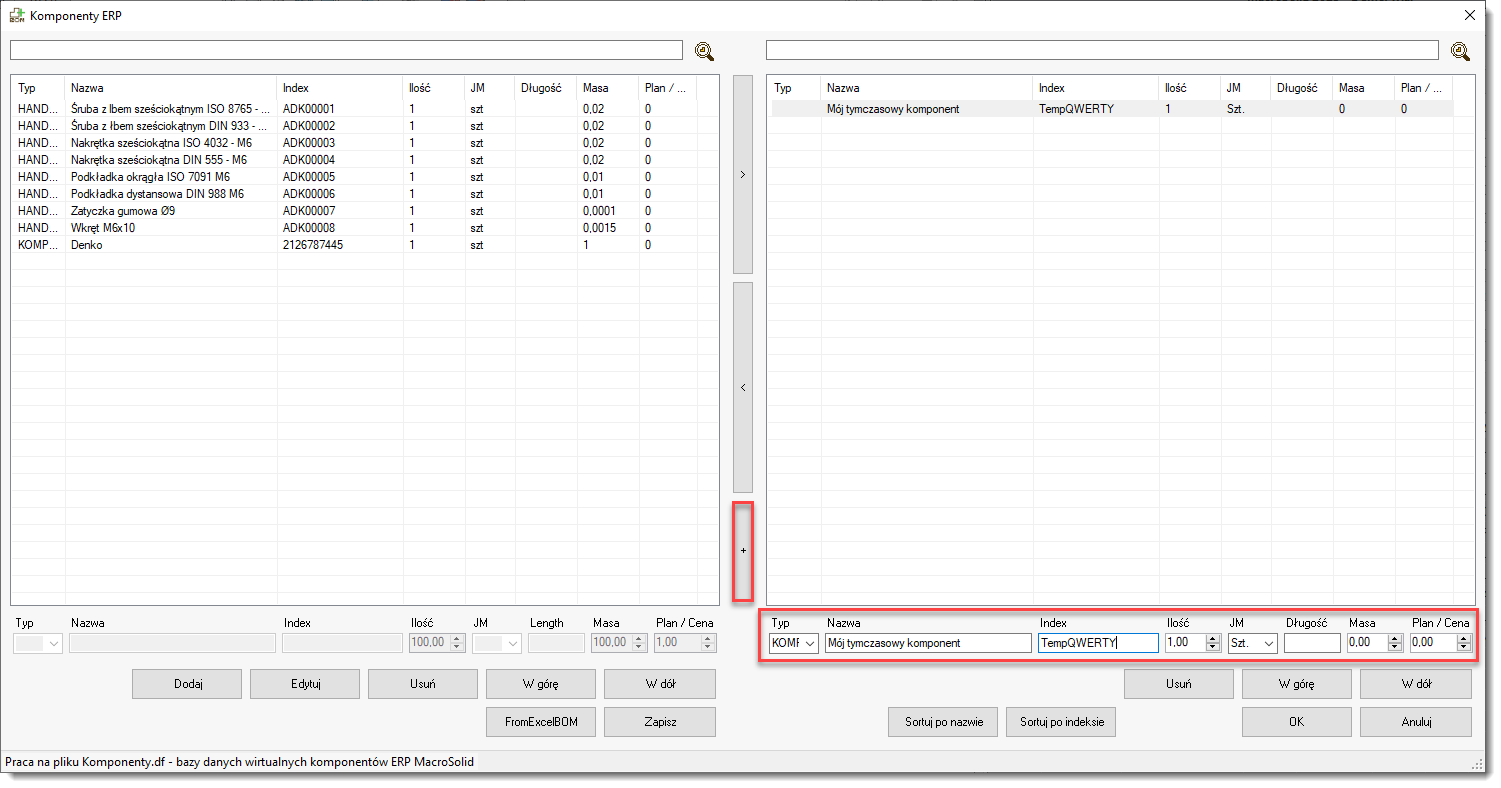
If stock levels are retrieved from the ERP system via CSV, there may be a need to add something to the SOLIDWORKS® project that doesn't yet exist in the ERP. In such cases, a temporary Virtual ERP Component needs to be created. We've got you covered.
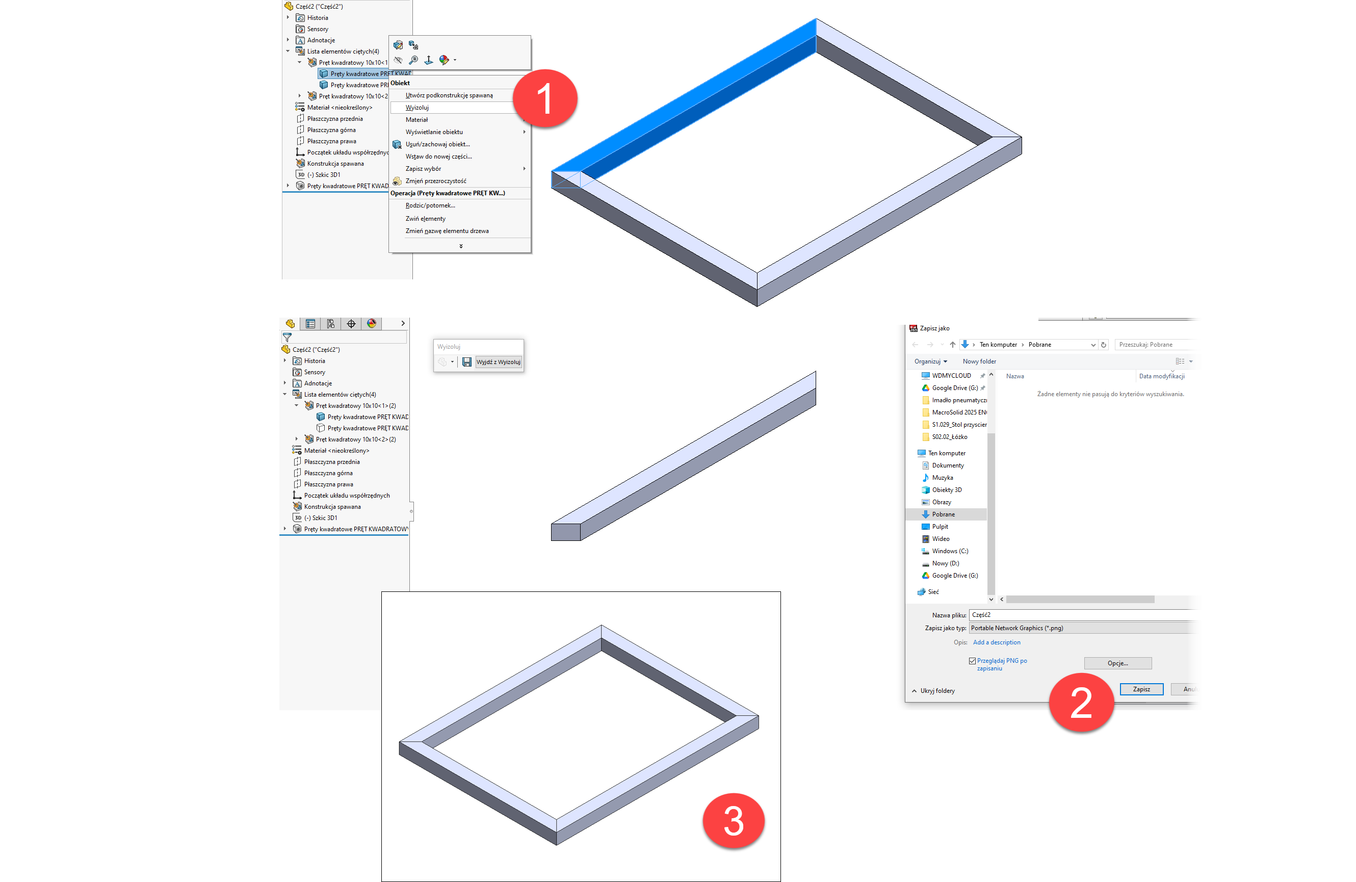
![]() SOLIDWORKS® 2025 took us by surprise. When using "Save As" to PNG from an isolated body, SOLIDWORKS® exits the isolation mode, which results in the entire assembly appearing in the image instead of just the single object. The issue has been reported, and we’re waiting along with you for a fix in the next Service Pack.
SOLIDWORKS® 2025 took us by surprise. When using "Save As" to PNG from an isolated body, SOLIDWORKS® exits the isolation mode, which results in the entire assembly appearing in the image instead of just the single object. The issue has been reported, and we’re waiting along with you for a fix in the next Service Pack.
MacroSolid v14.12.4
![]() And the final update in 2024 — this time, an update to Engraving.
And the final update in 2024 — this time, an update to Engraving.
Engraving is used to add a sketch with text onto a face, from which SOLIDWORKS® exports data to a DXF file. If the "Sketches" option is selected during DXF generation (either manually or via our DXF macro), all sketches that are not absorbed by features creating the model geometry will appear in the DXF file.
Using the appropriate mapping, these sketches can be exported in any color, font, style, and line thickness, and placed on a specified layer.
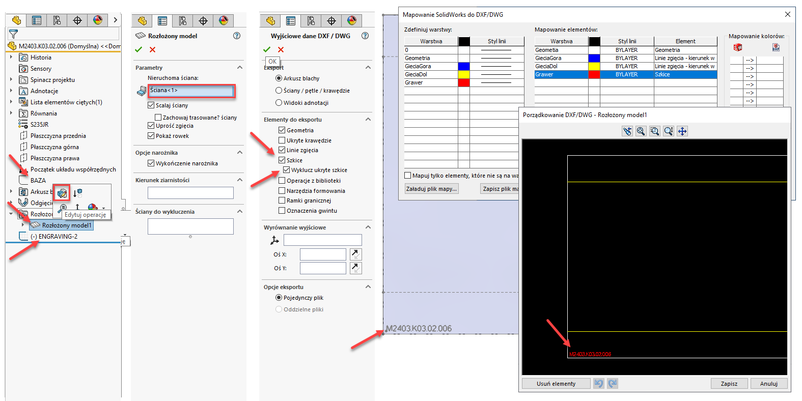
In the latest version of Engraving, we’ve decided to change the concept of how the sketch is added. Now, the sketch is placed on the flat pattern, i.e. under the "Flatten" feature, with two positioning options relative to the bounding frame: centered or in the bottom-left corner.
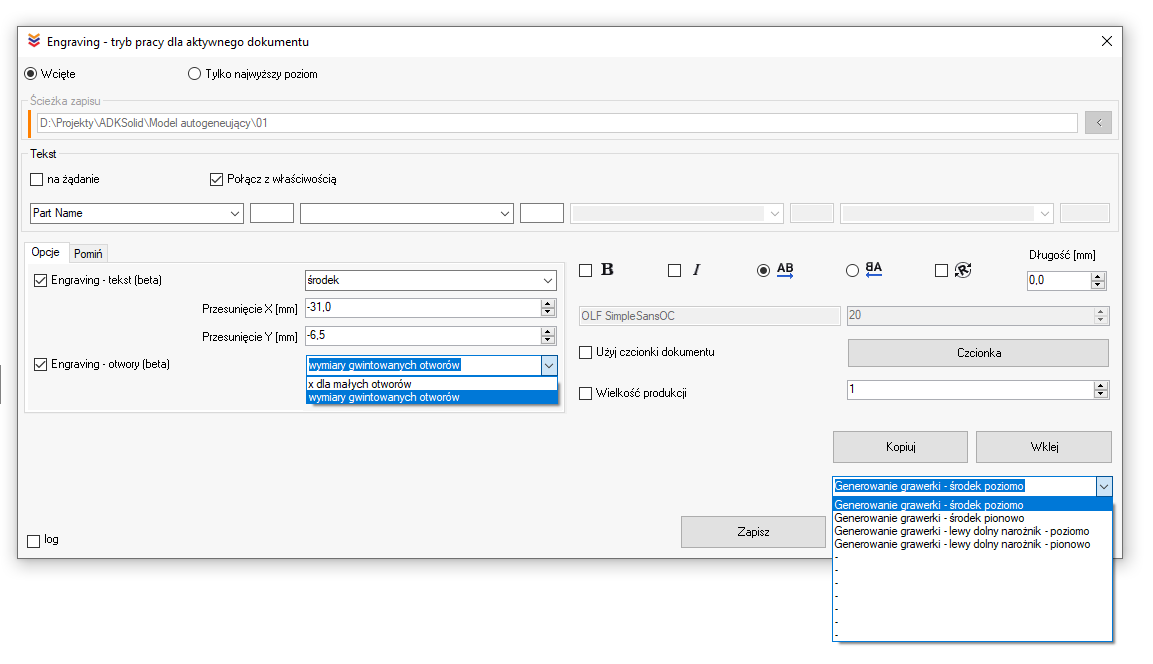
You can define multiple presets with different settings — such as X and Y offset from the insertion point, rotation, and font size — and then use these presets from the BOM Table depending on the dimensions and shape of the part. This brings significant potential for saving valuable minutes or even hours of your work.
Generate flat sheet images using the PIC macro, and while reviewing them, select the appropriate Engraving macro preset for each case.


In addition to engraving elements such as the number, file name, configuration name, or other data from custom or configuration-specific properties, the Engraving macro also allows for:
-
placing specifications and dimensions next to threaded holes, e.g. M10, uM8, vM6, where “u” indicates a hole with a cylindrical counterbore, and “v” a hole with a conical countersink, and
-
placing a cross (“X”) mark at the centers of holes smaller than the sheet thickness, along with their dimensions displayed nearby.
NOTES!!!
-
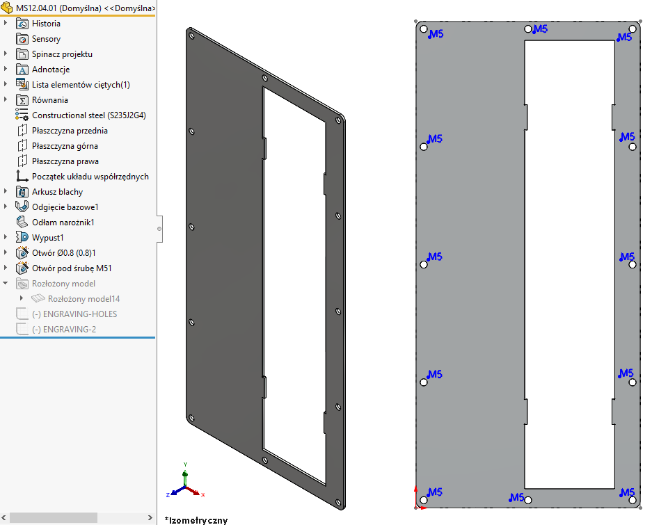
The functions work for single-body sheet metal parts where the fixed face is perpendicular or parallel to the main planes of the model.
-
For sheet metal parts where the fixed face is not perpendicular or parallel, the engraving text and threaded hole markings will still be added, but such parts will require verification and manual adjustment. For these cases, markings for holes smaller than the sheet thickness (the “X” symbol) will not be added.
-
Engraving does not support mirrored sheet metal parts.
-
Rolled sheet metal parts — i.e. those with a defined edge instead of a fixed face — are also problematic in terms of support.
-
Any problematic models will be logged and reported at the end of the generation process.
MacroSolid v14.11.9
![]() And one more major update this year — to the 2D drawing generation macro: DRAW.
And one more major update this year — to the 2D drawing generation macro: DRAW.
-
If you have the “Auto-scale new drawing views” option enabled in System Options > Drawings,
SOLIDWORKS® will automatically adjust the sheet scale to fit the model/view on the drawing when creating it. Great.
That said, we've added an option to force a specific sheet scale regardless of this behavior. -
You can now add views to the drawing along with annotations/dimensions already assigned to them.
-
For each main view, you can create projected views to the right, left, top, or bottom — optionally including annotation import.
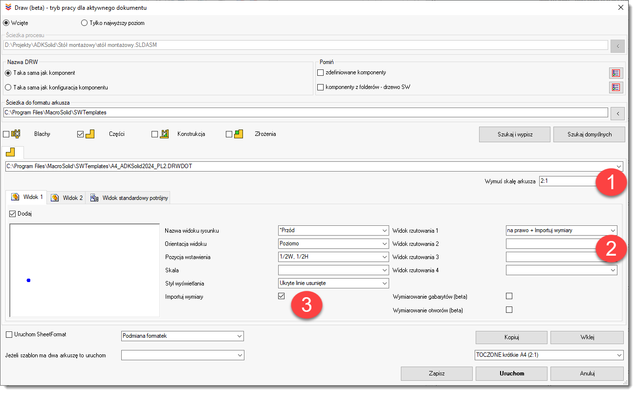
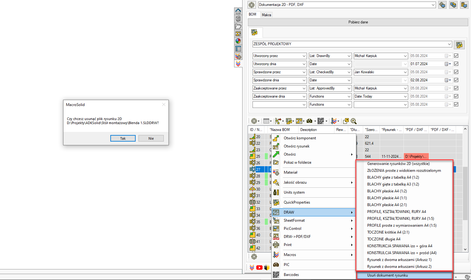
- We’ve adapted the Draw macro to work with two-sheet drawings / to create drawings with two sheets.
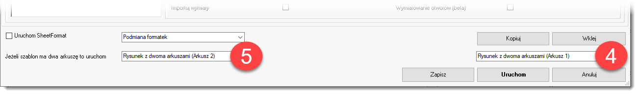
- In the BOM Table, you have up to 20 Draw macro presets available, along with a function that allows you to delete a drawing. The SLDDRW file will only be deleted after confirming a prompt message.
MacroSolid v14.9.3
MacroSolid has two modes: ADMINISTRATOR and DESIGNER.
The ADMINISTRATOR mode (default) provides full access to all software functions without any limitations.
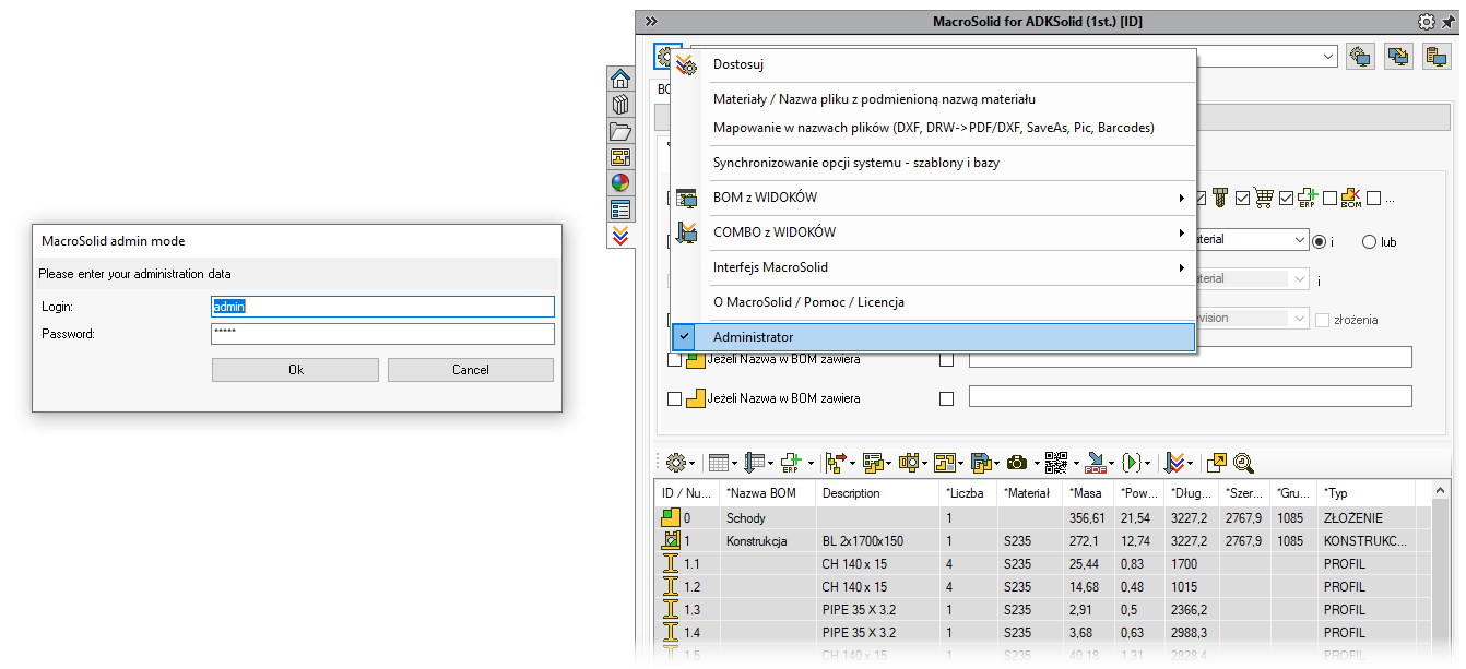
When ADMINISTRATOR mode is disabled (by removing login credentials), the system switches to DESIGNER mode. In this mode, the MacroSolid interface has certain limitations designed to protect the user from accidentally changing settings, misconfiguring features or macros, and unintentionally damaging the configuration developed for the company.
Limitations in DESIGNER mode include:
-
No right-click context menu for hiding or showing tabs
-
No context menu above the “Download data” button, where options for how data is retrieved from the model are located
-
Gear icons (which provide access to advanced configuration options) are unavailable
-
No ability to edit VIEWs
This allows you to deploy a dedicated version of MacroSolid tailored to your company's needs, with modification of its behavior locked down.
When configuring MacroSolid:
-
Decide which VIEWs should be available to all users and which only in ADMINISTRATOR mode
-
In each VIEW, hide unnecessary tabs — especially those that provide access to macro settings
-
Also hide the icons for editing and sorting the BOM table
-
Finally, remove the login credentials … and you're done.
The default login and password in the trial version are: admin, admin.
Each company that decides to implement MacroSolid receives its own installer and a customized software configuration. Every company individually decides whether designers will have access to all functionalities or will work under the DESIGNER account.
Get in touch with us, and we’ll define your configuration, your MacroSolid deployment scenario, and set up your login credentials.
MacroSolid v14.9.0
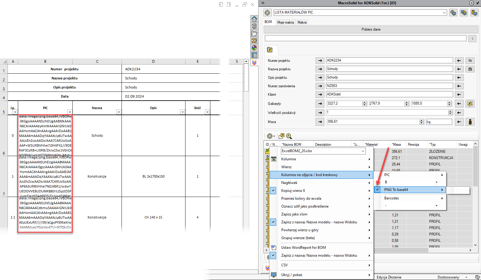
Sending a PNG image generated by the PIC macro to a database — for example, your ERP system or a web application — can be problematic. A new MacroSolid option can help by converting the PNG thumbnail into a base64 code format.
MacroSolid v14.8.0
You’ve probably encountered this issue before — while preparing 2D documentation for a sheet metal part, the data in the title block or notes was outdated or incorrect. Why does this happen? Most likely, the first view on your drawing sheet was a flat pattern view, meaning the properties were pulled from the configuration specific to the flat pattern.
That’s how SOLIDWORKS works — properties are taken from the model configuration used in the first view, or from the one defined in the sheet’s options.
How to fix this?
You need to remove the property from the “Flatten” configuration — ideally, remove all such properties. This is a derived sub-configuration, so if the drawing can’t find the property there, it will fall back to the parent configuration’s value.
Manually clearing these properties from every flat pattern in the project would be a huge time sink — so just use our new MacroSolid functionality to do it for you.
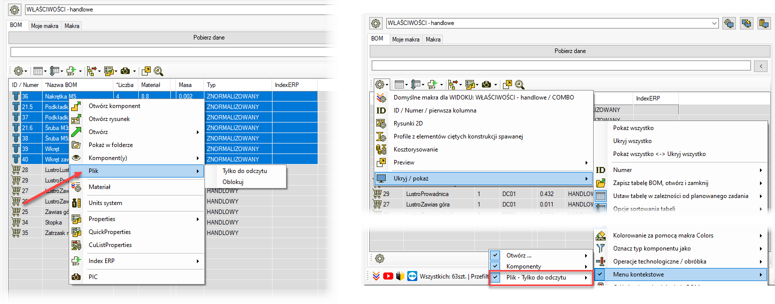
Cells in the first column will be highlighted in gray when a component file is in “Read-Only” mode. We’ve added the ability to manage the file status directly from the BOM Table.
However, please note that SOLIDWORKS® reads and retains this status when the model is opened, so after changing the file's status, you’ll need to reopen the model you’re working
MacroSolid v14.7.7
A new method for marking cells in the BOM Table — you can now identify values that already exist or are duplicated.
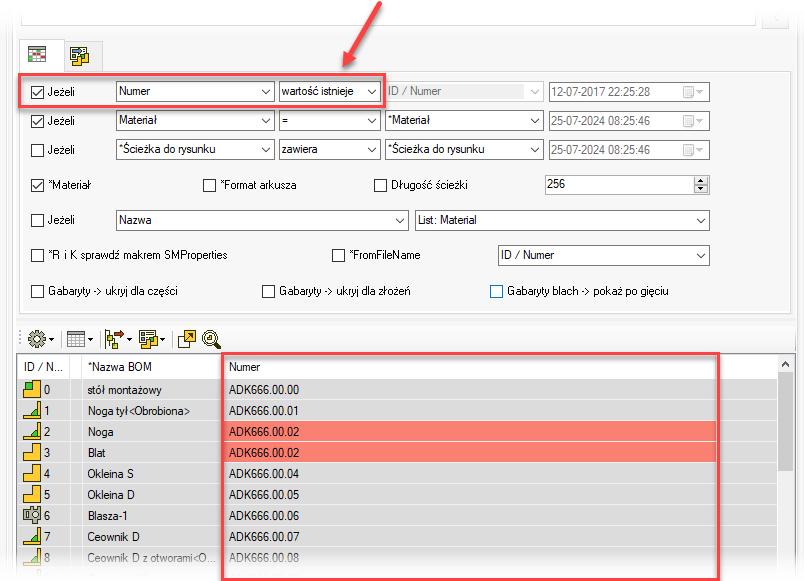
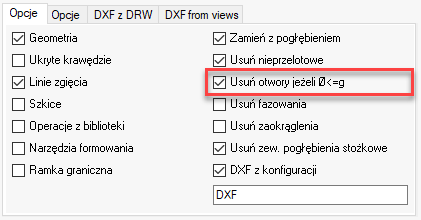
![]() DXF Macro – a new option has been added that removes holes (created using the Hole Wizard) from the generated DXF files if their diameter is less than or equal to the sheet metal thickness.
DXF Macro – a new option has been added that removes holes (created using the Hole Wizard) from the generated DXF files if their diameter is less than or equal to the sheet metal thickness.
MacroSolid v14.6.3
![]() Another update to the 2D drawing generation macro — DRAW.
Another update to the 2D drawing generation macro — DRAW.
We’ve added the ability to insert a Bill of Materials (BOM) for single-body sheet metal parts. Prepare your sldbomtbt template and link it in the macro settings, making sure that your DRWDOT drawing template already has a properly defined anchor point.
For single-body sheet metal parts, you can also add a note based on the information generated from the cut list properties.
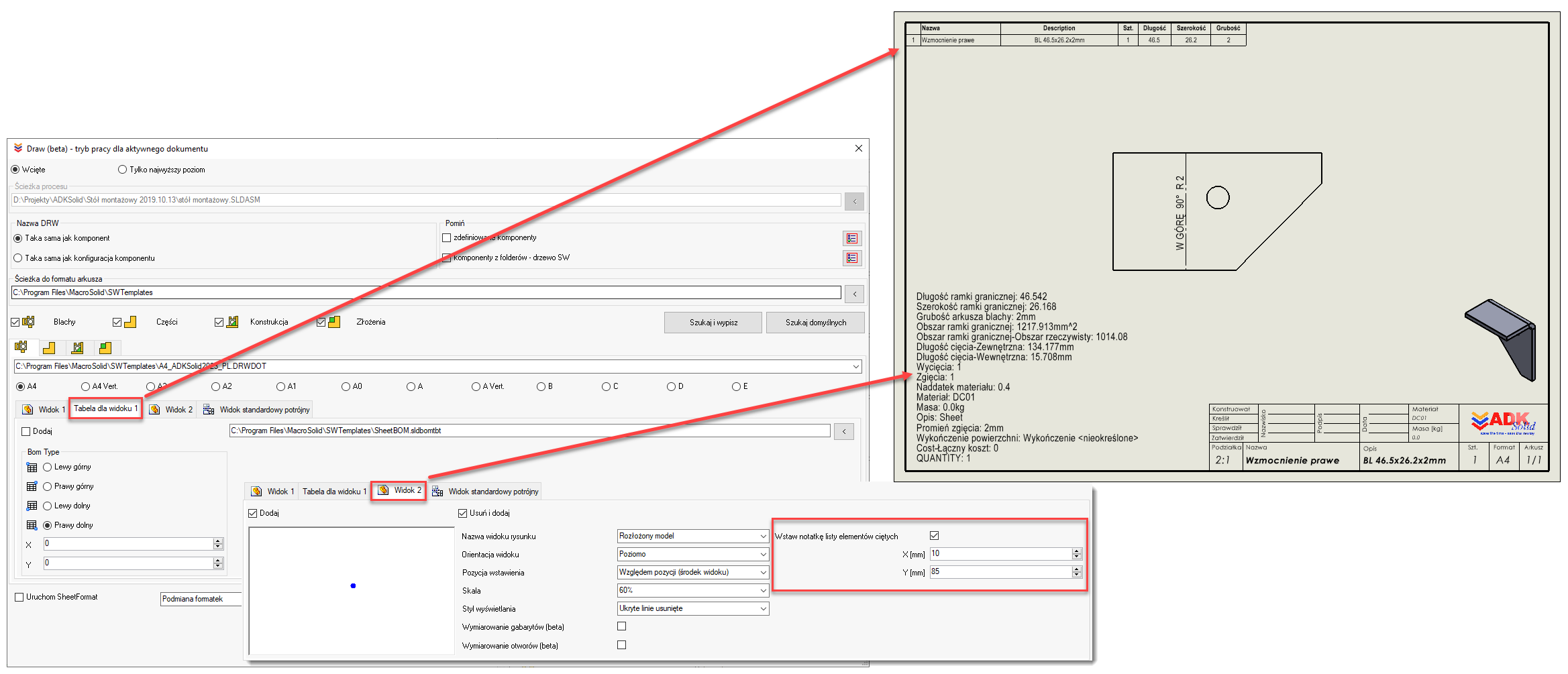
For assemblies, you can remove all existing Bills of Materials (sldbomtbt) and then insert a new one based on your custom template. This means you can update BOMs across all your older projects with a single click.
And one more important update to the DRAW macro — the ability to define multiple settings and save them under specific names allows you to plan and manage multiple flat documentation generation scenarios.
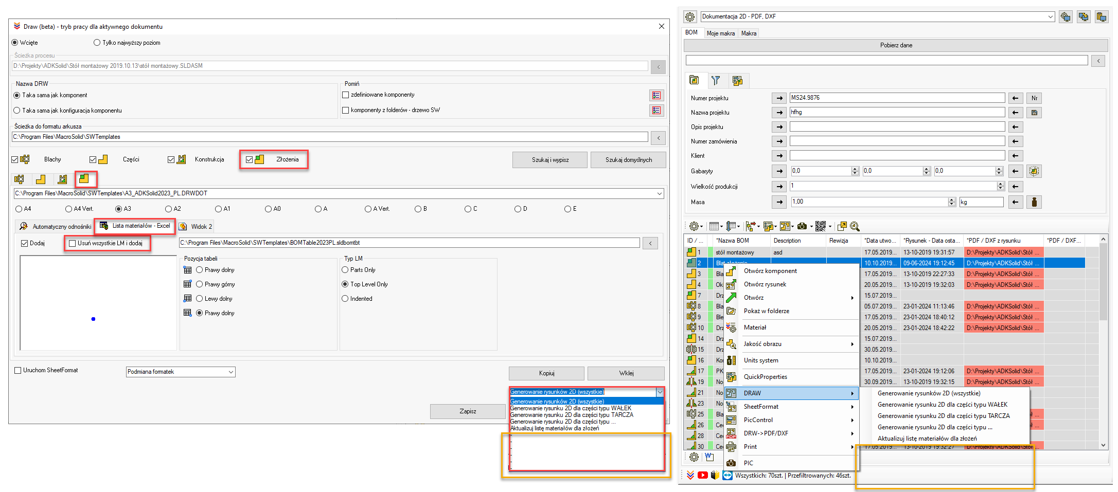
For all macros that support multiple settings — including the DRAW macro — we’ve introduced a hidden mechanism:
If you name a setting “-” or leave the name blank, it will not appear in the BOM tab. This lets you display only the configurations that are actually in use.
While we're at it, a quick reminder:
If you’re only seeing the default setting, it means the VIEW option “Show only default macros” is enabled.
And where do you define the default setting for a VIEW?
→ In the VIEW configuration settings, where you assign which macro setting should be treated as the default for that VIEW.
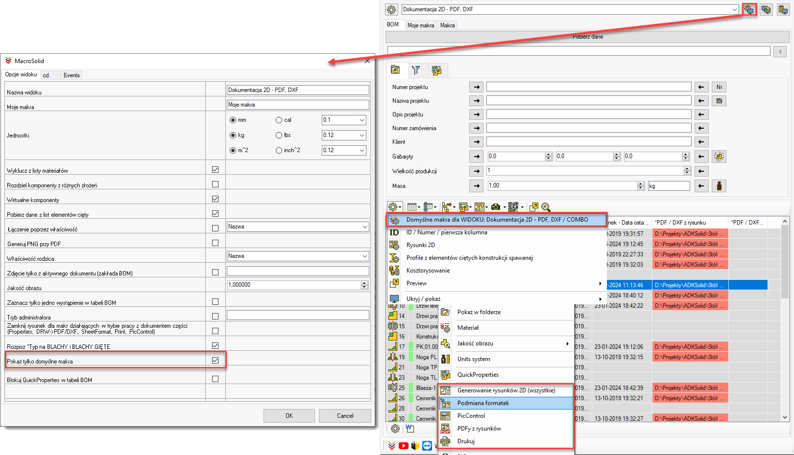
W oknie "Domyślne makra dla WIDOKu" ustawiamy domyśle makra dla WIDOKU, ale również sekwencję makr uruchamianych jednym kliknięciem. Funkcjonalność tą jak wiesz nazwaliśmy COMBO. Zapoznaj się z możliwościami tutaj.
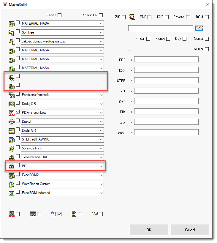
Makro PIC do generowania zdjęć do tej pory działało w jednej konfiguracji. Podobnie jak w makrze DRAW tak w makrze PIC dodaliśmy możliwość zdefiniowania wielu ustawień. Jedno z nich można przypisać do WIDOKu i wykorzystać w COMBO.
We’ve also linked to COMBO the macro that writes the quantity to properties (Quantity → Property) as well as the CutListProperties macro.
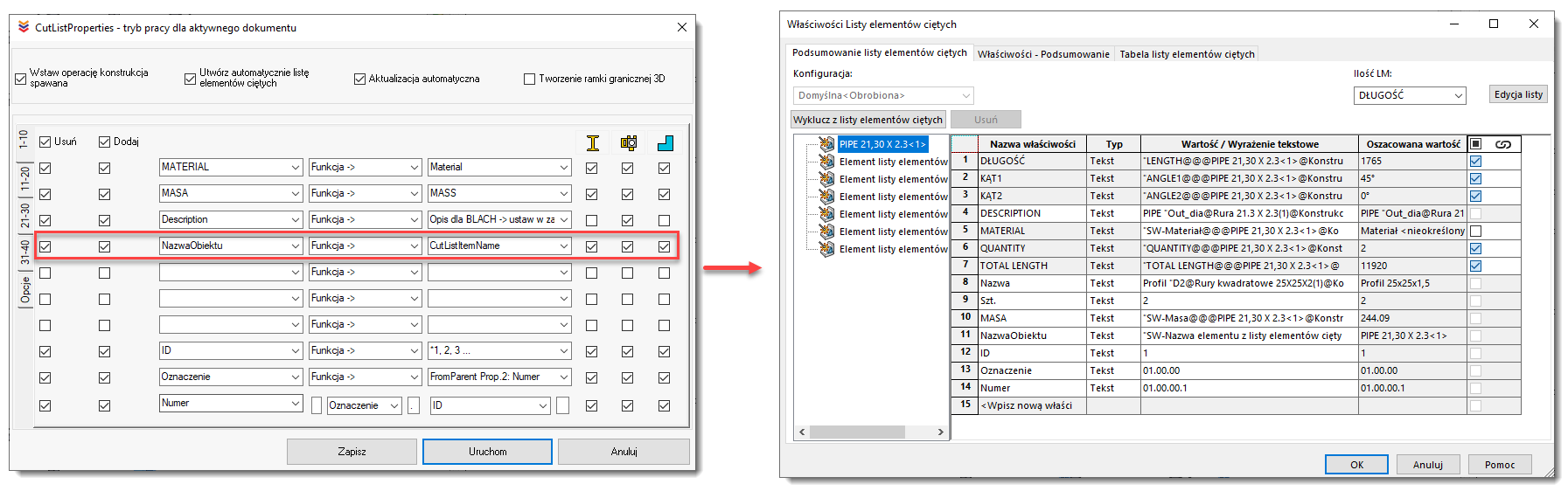
And we’ve enhanced the CutListProperties macro with additional methods for defining properties.
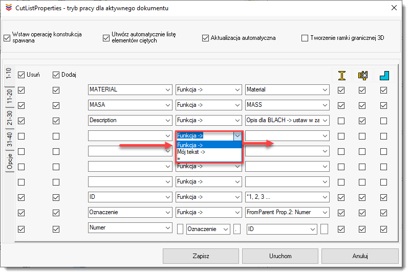
When you select "Function →", the control on the right is populated with available functions. For example, choosing Material will cause the macro to insert the appropriate SOLIDWORKS formula for defining a cut list property value, such as:SW-Material@@@PIPE 21,30 X 2.3<1>@Konstrukcja.SLDPRT.
Selecting options like *1, 2, 3 will result in the macro assigning sequential numbers to each body in a multi-body part.
We’ve also added a new function to the set: CutListItemName.
The result of this function is the cut list item name automatically generated by SOLIDWORKS.
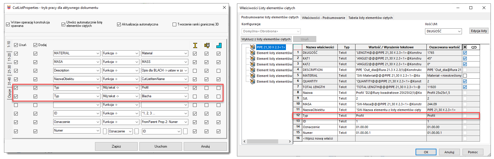
A new method for assigning values is allowing the macro to enter a value that you define manually.
When you select "My text →", the control on the right will populate with values you enter manually.
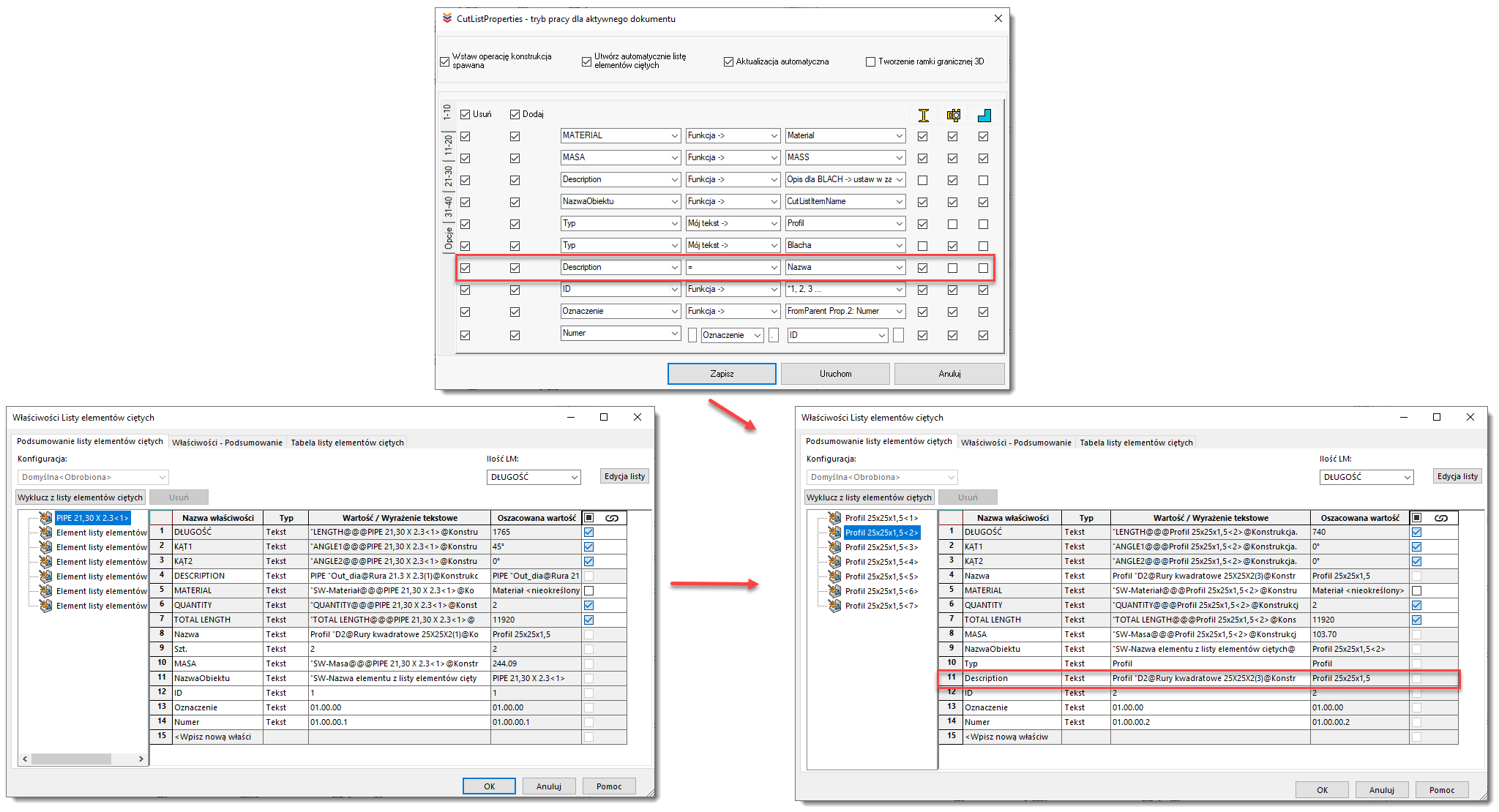
Nowa wersja CutListProperties posiada również możliwość zdefiniowania wartości na zasadzie "wartość taka sama jak". Wybierając "=" kontrolka po prawej stronie uzupełni się nazwami właściwości elementów ciętych. Przykład rezultatu działania nowej funkcjo poniżej.
The new version of CutListProperties also includes a method for assigning values based on the "same as" principle.
When you select "=", the control on the right will populate with the names of existing cut list properties.
MacroSolid v14.4.9
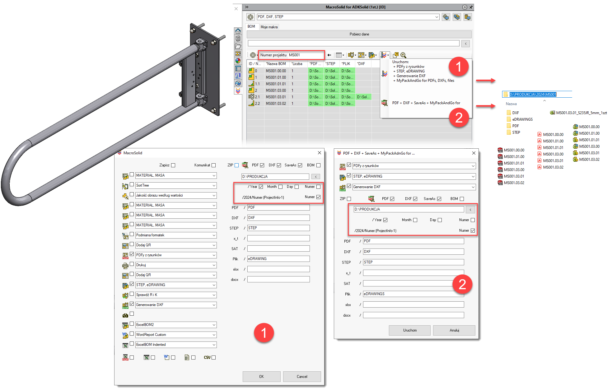
Both COMBO and the minimalist version MiniCOMBO can generate, with a single click, files in formats such as PDF, DXF, and additional ones like STEP and eDRAWING. A full description of these features can be found [here].
After generating the documentation in the project location, COMBO will copy the files to a specified destination — for example, a production server. This feature is called MyPackAndGo for PDF, DXF, STEP.
We’ve just added new sub-options that allow the target location to include automatically created subfolders — based on year, month, day, or even a custom number defined in the ProjectInfo tab.
MacroSolid v14.4.2
Global, batch renaming of files in a project
It seems the ideal situation is one where, during 3D CAD design and model preparation, the designer doesn’t have to think about file names at all. File names are usually determined by a company's internal numbering system.
However, the challenge is that during modeling, we often restructure the assembly tree — changing the order, adding or removing components, and reorganizing assemblies. That means we’re only able to assign proper file names and numbering at a later stage in the design process.
With the latest version of MacroSolid, this process has been automated — but a few key assumptions must be accepted for it to work properly.
🛑 Important Notes:
-
This functionality currently works only outside of PDM.
If your company uses PDM Professional, this isn’t needed — file names are managed by PDM’s built-in serial number generator.
🔧 Step-by-step Overview:
-
Start with the "Component Type" tab
You don’t want to rename models that represent purchased (commercial) components. MacroSolid must be able to identify and filter out purchased parts, so only manufactured parts get new names and corresponding 2D drawings. -
Work in a dedicated VIEW
Set up a special VIEW where purchased parts are filtered out. In this VIEW, you’ll plan and verify new file names before triggering the rename process. -
Use the two key columns:
-
The first column is editable and linked to a chosen custom property (e.g. Numer)
-
The second column,
*RenameDocument, is not editable — it mirrors the first column but is used to validate the planned names.
You’ll also see green highlights indicating that a model already has a corresponding SLDDRW drawing.
-
-
Plan your file names
While you can enter values manually, it's more efficient to use the QuickProperties macro, which generates sequential numbers for assemblies and parts. It can also build a full property using the project/order number and a structure-based counter. -
Verify using RenameDocument
-
The column highlights issues such as:
-
Duplicate file names within the same assembly session
-
Planned names that already exist in the save location
-
Invalid characters (according to Windows rules)
-
-
Red highlights indicate conflicts or errors that must be resolved.
-
-
Ready to rename?
If everything looks correct and no errors are flagged:-
Make a backup first (e.g. using PackAndGo) — highly recommended
-
Launch the RenameDocument function
-
The macro uses SOLIDWORKS' built-in renaming via the FeatureManager tree
-
-
After renaming:
-
Rebuild and save the entire model
-
Enable the checkbox “Update where used references” — this ensures all internal references update correctly
-
Finally, MacroSolid will rename the associated SLDDRW drawings
-
Beta Phase
This feature is currently in beta — you're invited to test it and share feedback as development continues.
It's a powerful step toward standardizing and automating file naming workflows after the modeling structure is stable, and especially useful for companies not using PDM.
MacroSolid v14.3.3
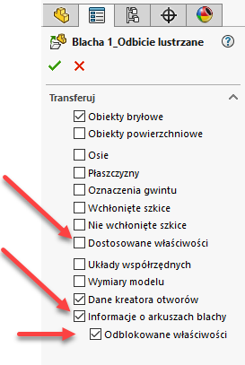
Podczas modelowania lustra blachy zwróć uwagę, aby przenieś informację o arkuszu blachy i odblokować jego właściwości. Proponuję również, aby nie transferować dostosowanych właściwości z oryginału. Jeżeli tego nie zrobisz wówczas lustro nie będzie widziane jako blacha a jako zwykła bryła o czym nasz dodatek poinformuje Cię odpowiednią ikoną w tabeli BOM. Jeżeli zaznaczysz przy transferze z oryginału „Dostosowane właściwości”, właściwości będą połączone z oryginałem a zatem nie przypiszesz do pliku innego opisu, numeru, uwagi.
When creating a mirror of a sheet metal part, make sure to:
-
Transfer the sheet metal definition properly
-
Unlock its properties
-
Avoid transferring custom properties from the original
If you don’t follow these steps, the mirrored part won’t be recognized as sheet metal but as a regular solid body — and our add-in will notify you with a corresponding icon in the BOM table.
Also, if you check “Custom properties” during the transfer from the original, the properties will remain linked to the source file. As a result, you won’t be able to assign a different description, number, or note to the mirrored part.
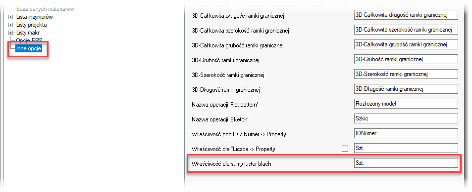
In the latest version of MacroSolid, we've added the ability to sum mirrored parts—that is, not to display them separately in the BOM table, but instead to add their quantity to the original. However, this assumes that these are sheet metal parts originating from a single-object file/model, which has one dimensional-material configuration.
In the case of mirrored sheet metal parts, it's common practice to create a single 2D drawing and include information indicating how many left- and right-handed versions there are. MacroSolid can help with this as well. If you define a dedicated property for this in the add-in options, it will be automatically filled in during data extraction with an appropriate entry showing the count of originals and mirrors, e.g., 1 + 7L. This can be a property linked on the drawing (e.g., 'Notes'), or it can be a special property used to store the quantity value.

Hide for single-body model' is a new filter that allows you to hide a body generated by 'Weldment'—specifically, a body originating from a single-body file. Profiles, structural shapes, pipes, flat bars, and rods from a multi-body file will still be visible in the BOM table.

MacroSolid v14.3.2
Browsing and assigning ERP indexes is handled by one of the functionalities of MacroSolid. Simply open the database window, filter and sort it, search for a component, and then assign it to a file or 3D CAD model body. The assignment will always apply to the selected row in the BOM table—“Name” will be copied to the property designated for the description, and “Index” to the property designated for the “ERP Index.”
If your company’s inventory and material management software—or the software that handles purchasing planning—can export inventory status to a CSV file, and if that export can be done automatically, periodically, and to a specific location, then that’s truly GREAT. The designer will have an up-to-date view of parts and materials and will be able to assign indexes to commercial components based on the current inventory.
Go to MacroSolid settings, under “ERP Options” and the “CSV Integration” tab. Enable the checkbox “Your ERP” and point to the CSV file. We designed this functionality to work with any CSV export, so you’ll also need to map the appropriate columns, so our importer knows where to find names, indexes, component type, units of measure, and even quantities and current stock levels.
MacroSolid v14.2.2
New MacroSolid feature – generating a number/index based on groups, categories, the file identifier from the PDM vault, and revision.
You assign a GROUP and CATEGORY to a file, and “on the fly” a new index is generated and saved to a property. However, the key element is the number, which must be unique. This is where the PDM identifier comes in—the ID assigned when the file is added to the vault. We’ve developed a feature that retrieves and saves the PDM file ID to a property.
Enable PDM integration, and in the MacroSolid settings, under the ERP Options tab, activate “ID from PDM.” Choose which property the ID should be saved to and what formatting should be applied. If you don’t use PDM Professional and only have the free Standard version, that’s not a problem. You’ll just need to provide connection details for a direct SQL database query.
In the settings, you can configure the index builder—i.e., select which property will store the GROUP value, CATEGORY value, and the ID. Additionally, we’ve included the option to build the index with the REVISION as part of it, either defined from a list or managed by the PDM through a workflow state change.
The list values must be maintained in text files. Each group has its own category list. When updating them, use the correct syntax: sequential numbers like 1, 2, 3 or 01, 02, 03, etc. After the number: space, dash, space, and then a description to help the designer understand what the group or category represents.
MacroSolid v14.1.0
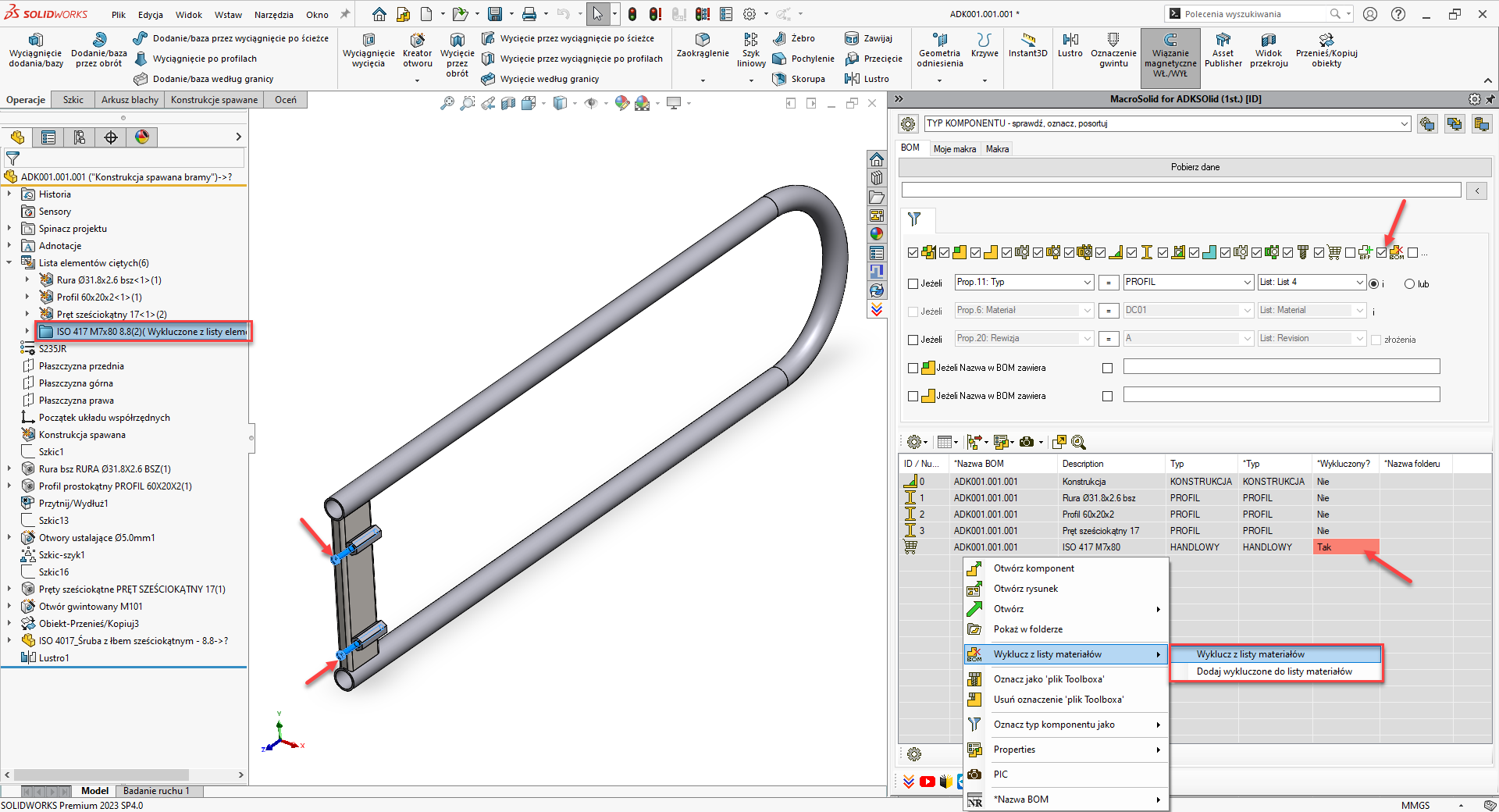
From the BOM table context menu, you can quickly mark a component as standardized or commercial. In practice, this means defining a document property that MacroSolid uses to identify such elements. We've added the ability to mark and identify standardized and commercial components that are bodies within a multi-body model.
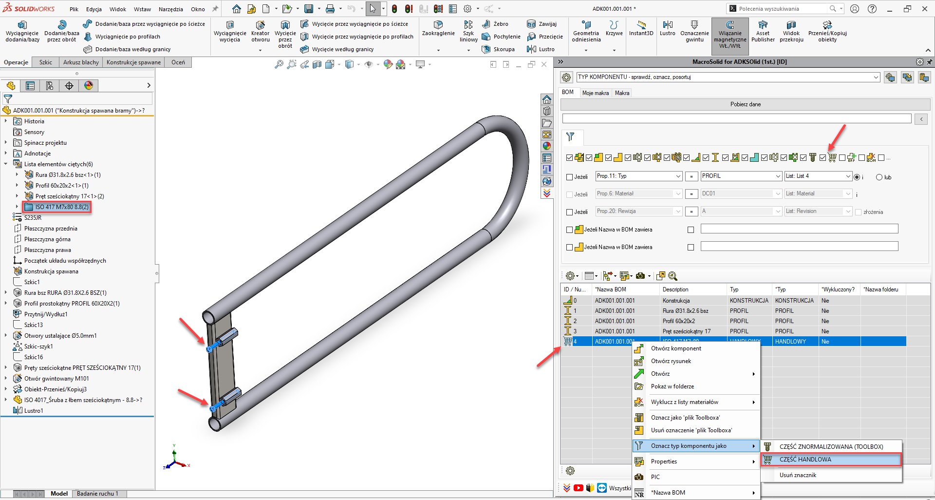
We have also improved the function that handles excluding items from the bill of materials directly from the BOM table by adding support for bodies within a multi-body model.
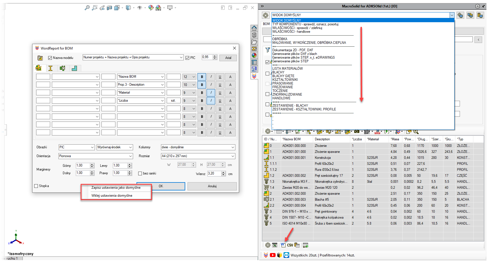
A small thing, but it will save a lot of time during configuration: save the settings of the macro that generates the MS Word® report to memory and paste them into other MacroSolid VIEWS.
Copyright © ADKSolid. All rights reserved.


