


BOM table
In the BOM table of the BOM tab, you can view the necessary data depending on the planned task (1). 40 columns (2) are planned to be used, in which it is possible to display information taken from the model, recalculated and/or checked by the MacroSolid add-in (3). One column can be assigned to display data for components (SLDPRT, SLDASM files), profiles, plates and regular solids from the CutList.
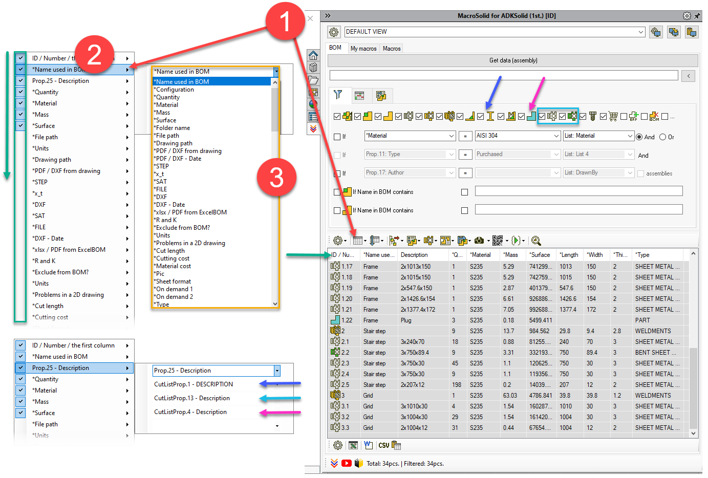
It is possible to display information inferred by MacroSolid, marked with * and information defined in the file properties, and in the case of multibody model solids, also information from the properties of cut elements.
- *Name used in BOM - the name displayed in the bill of materials. Typically, this is "Document Name", but for a model in configuration it can be "Configuration Name" or "User Specified Name".
- *Configuration - configuration name.
- *Quantity - number of instances downloaded by MacroSolid.
- *Material - material defined in the model.
- *Mass - mass of the model.
- *Surface - surface of the model.
- *Folder name - the name of the folder where the file is located.
- *File path - path to the SLDPRT or SLDASM document file.
- *Drawing path - path to the 2D drawing of the SLDPRT or SLDASM model.
- *PDF / DXF from drawing - path to a PDF or DXF file generated using the DRW->PDF/DXF macro from the default setting assigned to the VIEW.
- *PDF / DXF - Date - creation date of the PDF or DXF file generated using the DRW->PDF/DXF macro from the default setting assigned to the VIEW.
- *STEP - path to the STEP file generated using the SaveAs macro from the default setting assigned to the VIEW.
- *x_t - path to the x_t file generated with the SaveAs macro from the default setting assigned to the VIEW.
- *SAT - path to the SAT file generated with the SaveAs macro from the default setting assigned to the VIEW.
- *FILE - path to the file generated with the SaveAs macro from the default setting assigned to the VIEW.
- *DXF - path to the DXF file generated using the DXF macro from the default setting assigned to the VIEW.
- *DXF - Date - creation date of the DXF file generated using the DXF macro from the default setting assigned to the VIEW.
- *xlsx / PDF from ExcelBOM - path to the PDF file saved from the xlsx file generated with the ExcelBOM macro.
- *R and K - the value of the default R radius and K factor for plates, or after enabling the "*R and K check with the SMProperties macro" property information verified against the SMProperties macro setting.
- * Excluded? - yes or no - information whether the component has been excluded from the list of materials.
- *Units - document unit.
- *Problems in a 2D drawing - a special column in which problems and errors in a 2D drawing are listed, identified with the "Check 2D drawings" function.
- *Cut length - the total cut length taken from the unfolded sheet as the sum of the length of the external and internal cuts.
- *Cutting cost - the cost of cutting calculated based on the "QuickCosting" settings.
- *Material cost - material cost calculated on the basis of "QuickCosting" settings.
- *Pic - path to the photo generated with the PIC macro.
- *Sheet format - name of the SLDDRT drawing format used in the 2D drawing, checked with the "SheetFormat - check" or "Check 2D drawings" function.
- *On Demand 1 - column displaying data as agreed or at the Customer's request.
- *On Demand 2 - a column displaying data as agreed or at the Customer's request.
- *Type - component type according to the MacroSolid recognition algorithm: COMPONENT, SHEET METAL, BENDED SHEET, STRUCTURE, PROFILE, ASSEMBLY, COMMERCIAL.
- *Index ERP - data from the FromExcelBOM.xlsx file inferred based on the component type.
- *Parent - *BOM name of the parent.
- *Level - the level at which the component is located in the FeatureManager tree structure.
- *Length - the largest dimension for parts and assemblies. In the case of sheet metal *Length is the "length of the bounding frame" unless the "Sheet metal dimensions -> show after bending" option is enabled. It is possible to hide the *Length value for all components except sheet metal and for assemblies.
- *Width - intermediate size for parts and assemblies. In the case of sheet metal *Width is the "border frame width" unless the " dimensions -> after bending" option is enabled. You can hide the *Width value for all components except sheet metal and for assemblies.
- *Thickness - the smallest overall dimensions for parts and assemblies. In the case of plates *Thickness is the "thickness of the border frame" unless the "Dimensions -> after bending" option is enabled. You can hide the *Thickness value for all components except sheet metal and for assemblies.
- *File - Last Saved Date - date of the last save of the SLDPRT / SLDASM document.
- *Drawing - Last Saved Date - date of last saving of the drawing SLDDRW.
- *Quantity x Production volume - the result of multiplying the number of component pieces with the production quantity defined in the ProjectInfo tab.
- *PDF specification - name of the PDF file of the commercial component specification. If a value appears in the *PDF specification column, it means that a file with the same name was found in the folder or subfolders of the trade component save location, and therefore it will be possible to transfer such a file using the "Copy trade component PDFs to" function.
- *Read-only - status of the file attribute "Read-only". In addition, the first column will be highlighted in red if the file is not writable.
- *Date created - creation date of the SLDPRT or SLDASM document.
- *Date modified - modification date of the SLDPRT or SLDASM document.
- *Image quality - deviation value in the "Image quality" tab of the document properties.
- *File problems - a special column in which model problems identified by the SMProperties macro are listed.
- *Qty. / Parent Qty. - the result of dividing the number of pieces of a component by the number of pieces of the assembly in which this component is located.
- *Qty. * *Weight - the result of multiplying the number of component pieces with the mass of the model.
- *External references - information whether the file has an external reference.
- *Color - a color defined at the component level and compared in terms of RGB with the palette defined in the Color macro.
- *Density - the density of the material assigned to the model or solid.
You can save the BOM table to a file as well as recreate the component structure from a file.
Copyright © ADKSolid. All rights reserved


